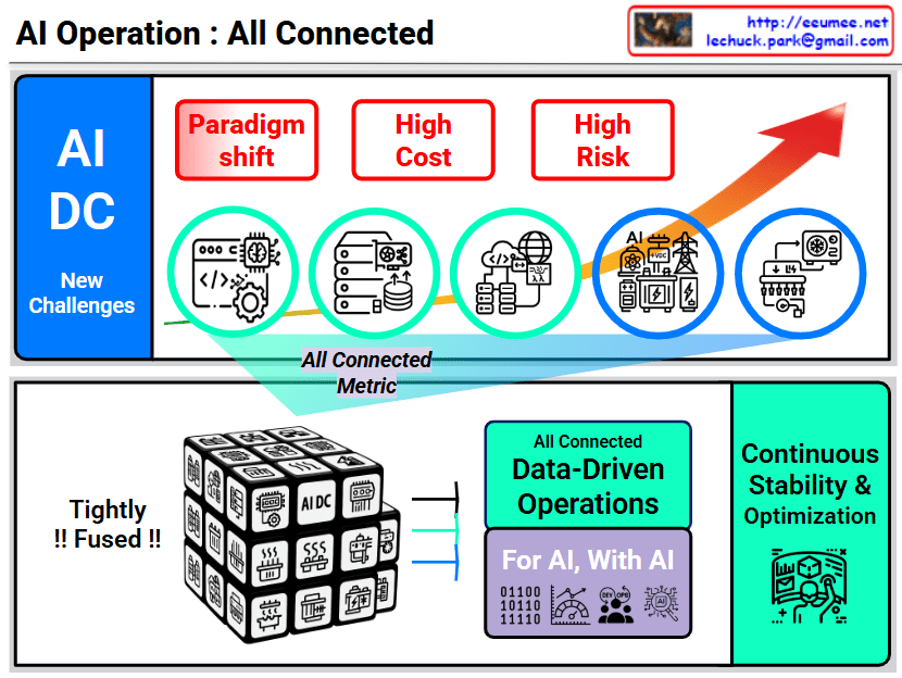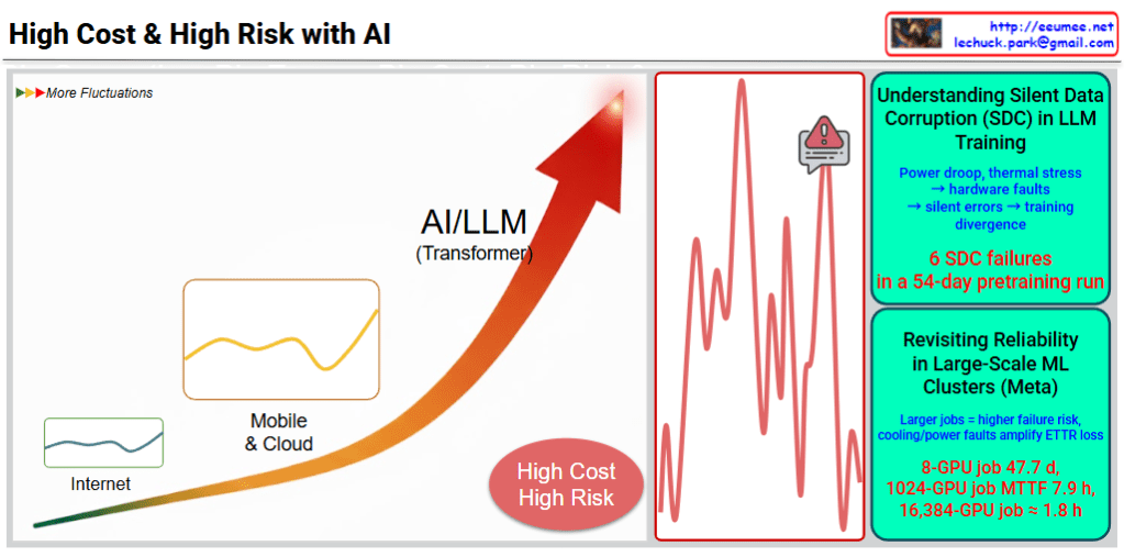
AI Data Center: Critical Bottlenecks and Technological Solutions
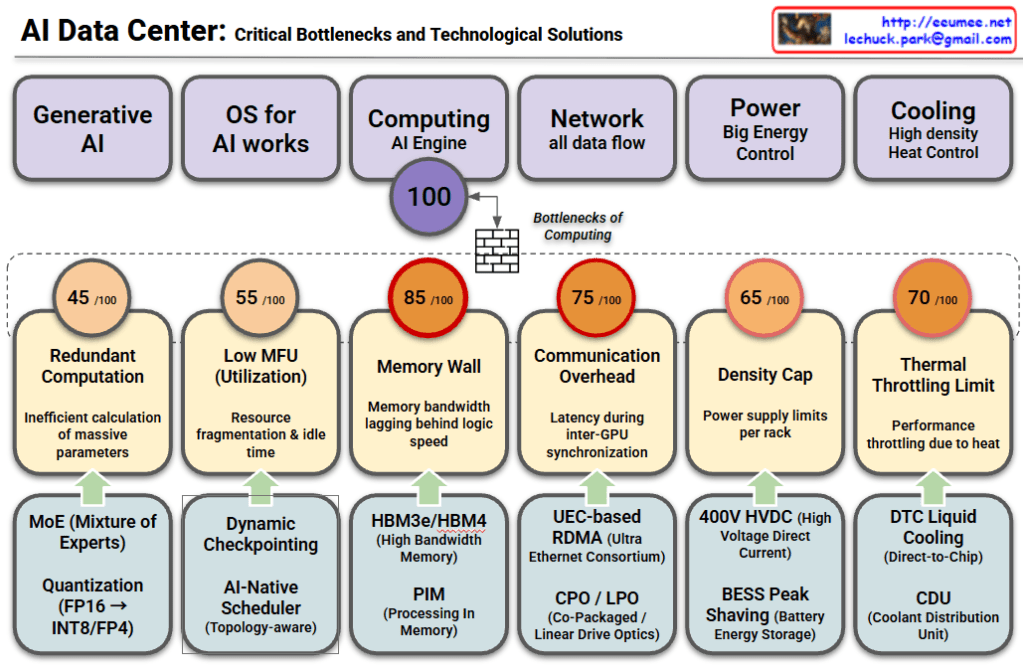
This chart analyzes the major challenges facing modern AI Data Centers across six key domains. It outlines the [Domain] → [Bottleneck/Problem] → [Solution] flow, indicating the severity of each bottleneck with a score out of 100.
1. Generative AI
- Bottleneck (45/100): Redundant Computation
- Inefficiencies occur when calculating massive parameters for large models.
- Solutions:
- MoE (Mixture of Experts): Uses only relevant sub-models (experts) for specific tasks to reduce computation.
- Quantization (FP16 → INT8/FP4): Reduces data precision to speed up processing and save memory.
2. OS for AI Works
- Bottleneck (55/100): Low MFU (Model Flops Utilization)
- Issues with resource fragmentation and idle time result in underutilization of hardware.
- Solutions:
- Dynamic Checkpointing: Efficiently saves model states during training.
- AI-Native Scheduler: Optimizes task distribution based on network topology.
3. Computing / AI Engine (Most Critical)
- Bottleneck (85/100): Memory Wall
- Marked as the most severe bottleneck, where memory bandwidth cannot keep up with the speed of logic processors.
- Solutions:
- HBM3e/HBM4: Next-generation High Bandwidth Memory.
- PIM (Processing In Memory): Performs calculations directly within memory to reduce data movement.
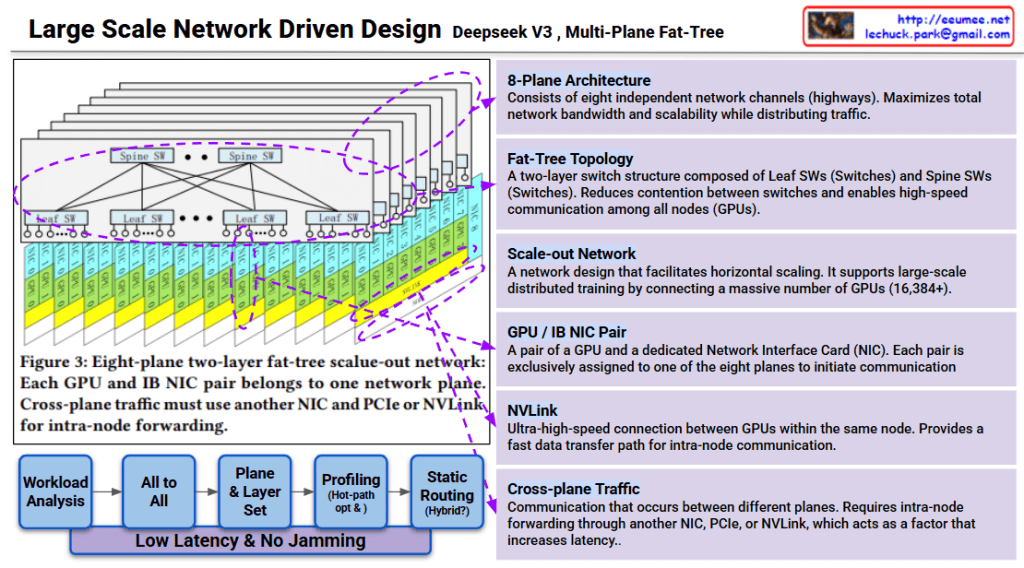
4. Network
- Bottleneck (75/100): Communication Overhead
- Latency issues arise during synchronization between multiple GPUs.
- Solutions:
- UEC-based RDMA: Ultra Ethernet Consortium standards for faster direct memory access.
- CPO / LPO: Advanced optics (Co-Packaged/Linear Drive) to improve data transmission efficiency.
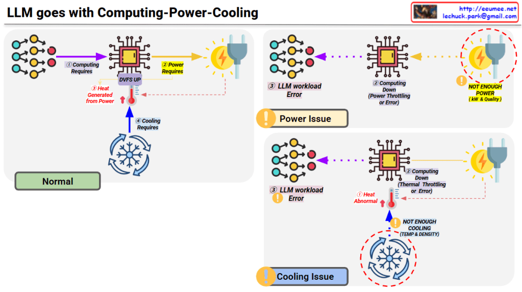
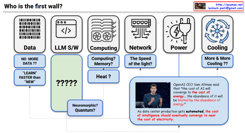
5. Power
- Bottleneck (65/100): Density Cap
- Physical limits on how much power can be supplied per server rack.
- Solutions:
- 400V HVDC: High Voltage Direct Current for efficient power delivery.
- BESS Peak Shaving: Using Battery Energy Storage Systems to manage peak power loads.
6. Cooling
- Bottleneck (70/100): Thermal Throttling Limit
- Performance drops (throttling) caused by excessive heat in high-density racks.
- Solutions:
- DTC Liquid Cooling: Direct-to-Chip liquid cooling technologies.
- CDU: Coolant Distribution Units for effective heat management.
Summary
- The “Memory Wall” (85/100) is identified as the most critical bottleneck in AI Data Centers, meaning memory bandwidth is the primary constraint on performance.
- To overcome these limits, the industry is adopting advanced hardware like HBM and Liquid Cooling, alongside software optimizations like MoE and Quantization.
- Scaling AI infrastructure requires a holistic approach that addresses computing, networking, power efficiency, and thermal management simultaneously.
#AIDataCenter #ArtificialIntelligence #MemoryWall #HBM #LiquidCooling #GenerativeAI #TechTrends #AIInfrastructure #Semiconductor #CloudComputing
With Gemini