Adaptive Congestion Control

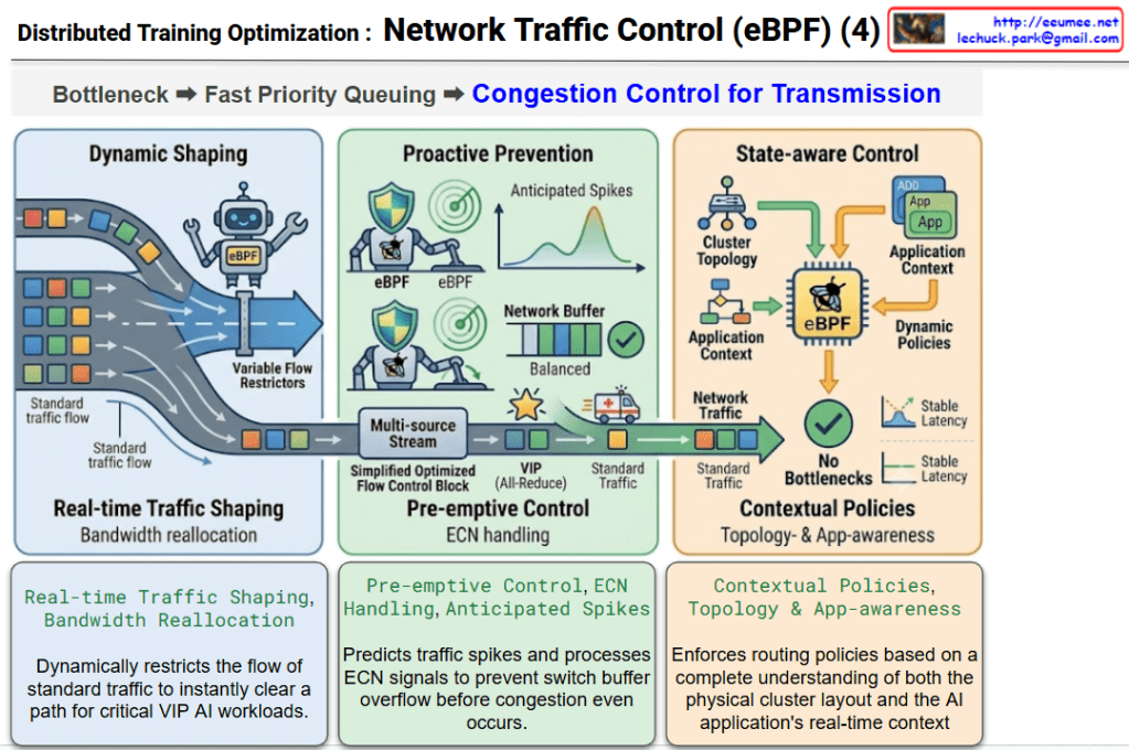
This infographic illustrates the three core mechanisms of “Adaptive Congestion Control,” showcasing how an eBPF-based controller goes beyond simple packet filtering to actively and intelligently manage network congestion in real-time.

1. Dynamic Shaping (Left Panel / Blue)

  • Keywords: Real-time Traffic Shaping, Bandwidth Reallocation
  • Description: Depicts an eBPF robot operating “Variable Flow Restrictors.” It performs real-time traffic shaping by dynamically adjusting the bandwidth allocated to standard traffic flows. It effectively narrows the path for regular packets to make room when critical VIP traffic needs to pass through.

2. Proactive Prevention (Center Panel / Green)

  • Keywords: Pre-emptive Control, ECN Handling, Anticipated Spikes
  • Description: Shows eBPF robots equipped with shields and radars, indicating the ability to foresee “Anticipated Spikes” in traffic. It handles ECN (Explicit Congestion Notification) to pre-emptively control flow and maintain balanced network buffers before overflow occurs. The bottom section visualizes VIP (All-Reduce) traffic bypassing standard traffic smoothly, akin to an ambulance clearing a traffic jam.

3. State-aware Control (Right Panel / Orange)

  • Keywords: Contextual Policies, Topology & App-awareness
  • Description: Illustrates the eBPF chip receiving data from both the “Cluster Topology” and the “Application Context.” This means the controller doesn’t just look at packets blindly; it enforces Dynamic Policies based on a holistic understanding of the AI application’s state and hardware layout, ultimately resulting in “No Bottlenecks” and “Stable Latency.”

๐Ÿ“ Summary

This diagram clearly visualizes the complete mechanism of Adaptive Congestion Control, where the eBPF controller 1) dynamically shapes bandwidth in real-time, 2) proactively prevents congestion by anticipating spikes, and 3) acts with full topology and application awareness to ensure uninterrupted, optimized network performance for AI workloads.

#AdaptiveCongestionControl #DynamicShaping #ProactivePrevention #StateAwareControl #eBPF #ECN #TrafficShaping #AINetworkOptimization

With Gemini
eBPF Traffic Controller Core Technologies

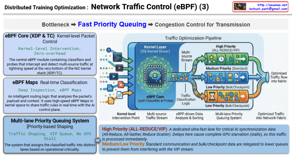
This section illustrates the control phase where mixed application traffic (Multi-source Stream) is intercepted at the lowest level of the OS, analyzed, and sorted into multiple lanes based on priority to ensure an optimized traffic flow into the network fabric.

  • eBPF Core (XDP & TC) [Kernel-level Packet Control]
    • Keywords: Kernel-level Intervention, Zero-overhead
    • Core: The central eBPF module containing classifiers and probes that intercept and detect multi-source traffic at lightning speed at the very bottom of the NIC kernel stack (XDP/TC).
  • Traffic Classification Logic (Powered by eBPF Maps) [Real-time Classification]
    • Keywords: Deep Inspection, eBPF Maps
    • Core: An intelligent routing logic that analyzes the packet’s payload and context. It uses high-speed eBPF Maps in kernel space to share traffic rules in real-time with the AI control plane.
  • Multi-lane Priority Queuing System [Priority-based Shaping]
    • Keywords: Traffic Shaping, VIP Queue, No GPU Stall
    • Core: The system that assigns the classified traffic into distinct lanes based on operational criticality.
      • High Priority (ALL-REDUCE/VIP): A dedicated ultra-fast lane for critical AI synchronization data (All-Reduce, All-Gather, Reduce-Scatter). Delays here cause complete GPU starvation (stalls), so this traffic is processed immediately.
      • Medium/Low Priority: Standard communication and bulk/checkpoint data are relegated to lower queues to prevent them from interfering with the VIP stream.

๐Ÿ“ Summary (Summary)

The eBPF Traffic Controller acts as an intelligent traffic cop inside the OS kernel. By identifying potential bottlenecks early and aggressively steering vital collective communication data (like All-Reduce) into Fast Priority Queues (VIP), it completely eliminates GPU starvation and ensures continuous, high-efficiency model training.

#eBPF #TrafficController #XDP_TC #PriorityQueuing #ZeroGPUStall #AllReduce #AllGather #NetworkOptimization

With Gemini

Distributed Training Optimization : Network Traffic Control (eBPF) – Bottleneck

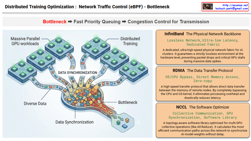
This infographic intuitively visualizes the “Bottleneck” phaseโ€”the very first step in network optimization for large-scale AI distributed training environments. It also outlines the three foundational infrastructure technologies involved in this process. As indicated by the red highlight on the word Bottleneck in the top workflow process, this specific diagram is entirely focused on defining the problem area.

1. Visual Context Description (Left Illustration)

  • The graphic on the left depicts a Massive Parallel GPU workloads environment, where numerous GPU clusters are operating simultaneously.
  • “Diverse Data” pouring out from each distinct GPU node converges into a massive, funnel-like channel labeled “DATA SYNCHRONIZATION.”
  • The illustration brilliantly captures a severe “Bottleneck” occurring as a massive volume of data packets (represented by the colorful blocks) attempts to squeeze through this narrow passage all at once, causing a massive traffic jam.

2. Core Infrastructure Technologies (Right Panels) The right side details the three core infrastructure stacks where this physical and logical data synchronization (and the resulting bottleneck) takes place.

  • InfiniBand (The Physical Network Backbone): A dedicated, ultra-high-speed physical network fabric for AI clusters. It guarantees a strictly lossless environment at the hardware level, preventing packet drops and critical GPU stalls during massive data spikes as seen on the left.
  • RDMA (The Data Transfer Protocol): A high-speed transfer protocol that allows direct data transfer between the memory of remote nodes. By completely bypassing the CPU and OS kernel, it eliminates processing overhead and drastically reduces latency.
  • NCCL (The Software Optimizer): A topology-aware software library optimized for multi-GPU collective operations (like All-Reduce). It calculates the most efficient communication paths across the network to synchronize AI model weights without delay.

๐Ÿ“ Summary

This diagram defines the problem state by using a funnel metaphor to visualize the inevitable network bottleneck that occurs when multiple GPUs synchronize data during distributed AI training. Simultaneously, it serves as an introductory technical overview, clearly outlining the keyword-centric roles of the underlying infrastructure stackโ€”InfiniBand, RDMA, and NCCLโ€”that handles this immense traffic.

#AIInfrastructure #DistributedTraining #NetworkBottleneck #DataCenter #InfiniBand #RDMA #NCCL #GPUCluster

With Gemini

Distributed Training Optimization : Network Traffic Control (eBPF)

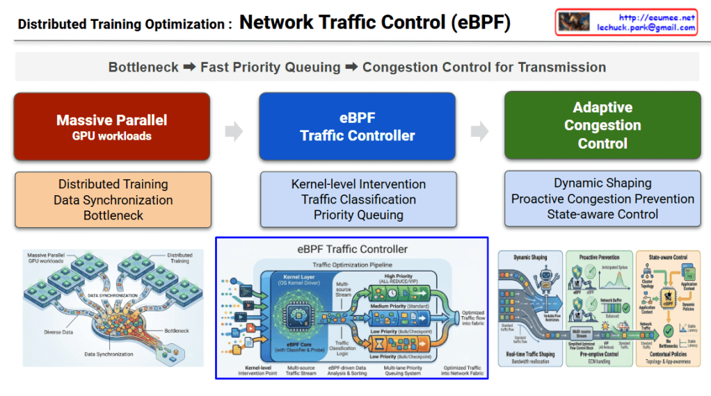
The diagram, titled “Distributed Training Optimization: Network Traffic Control,” outlines a core 3-stage optimization pipeline. It logically unfolds the process of identifying and solving the problem following the top flow path: Bottleneck โžก๏ธ Fast Priority Queuing โžก๏ธ Congestion Control for Transmission.

1. Massive Parallel GPU Workloads

  • Visual Description: The red section on the left and the illustration below it depict “Diverse Data” pouring out from multiple GPU cluster nodes and converging into a single, narrow bottleneck.
  • Core Meaning: It illustrates the Data Synchronization traffic that is essential during the Distributed Training of AI models. It structurally highlights the inevitable network bottleneck that occurs when countless GPUs attempt to exchange computational results simultaneously.

2. eBPF Traffic Controller

  • Visual Description: The central blue section introduces the core control engine designed to resolve the aforementioned bottleneck. The lower illustration shows complex traffic being neatly sorted into three pipes (priority lanes) at the OS Kernel Driver layer.
  • Core Meaning: It demonstrates Kernel-level Intervention, allowing access to network packets without massive overhead. Following the Traffic Classification logic, the system implements Priority Queuing: mission-critical traffic directly affecting training speed (like All-Reduce) is routed to the top ‘High Priority (VIP)’ queue, while standard storage traffic goes to the ‘Low Priority’ queue.

3. Adaptive Congestion Control

  • Visual Description: The green section on the right depicts the dynamic management of queued traffic as it is transmitted into the actual network fabric. The illustration shows eBPF agents adjusting valves in real-time (Dynamic Shaping), predicting and preventing network spikes (Proactive Prevention), and maintaining stable traffic flow based on the overall application context (State-aware Control).
  • Core Meaning: Beyond simple prioritization, it proactively monitors network switch buffer states and overall infrastructure congestion to flexibly adjust transmission rates. Ultimately, this creates a flawless, optimized data flow with zero latency.

๐Ÿ“ Summary

This diagram visualizes the complete pipeline for maximizing communication efficiency in AI data centers. To resolve the inevitable network bottlenecks caused by AI distributed training, it introduces an eBPF-based traffic controller operating at the lowest kernel level to prioritize traffic, and executes adaptive congestion control reflecting real-time network states to ensure seamless data transmission.

#AIDataCenter #eBPF #DistributedTraining #TrafficControl #InfrastructureEngineering #GPUCluster #AIOps #NetworkOptimization

With Gemini

AI Flame Graphs (eBPF)

๐Ÿ“Š AI Flame Graphs (eBPF) Architecture Diagram Interpretation

This diagram visually unfolds three logical stages (Problem Identification, Technical Solution, and Derived Results) based on the core theme stated at the top: “Tracks bottlenecks caused by CPU-GPU asynchronous execution.”.

1. ๐Ÿ”ด Problem Identification (Left Red Section) This area highlights the fundamental issue of losing visibility due to asynchronous processing.

  • Disconnected Execution Flow: The gray blocks illustrate the execution stack, where commands originating from the Application (PyTorch) pass through the C++ Runtime, down to the Kernel Driver, and finally to the GPU Hardware.
  • Asynchronous Nature: The large downward arrow on the left emphasizes that this entire process occurs “asynchronously between the CPU and GPU.”
  • Resulting Limitation: As stated in the orange box at the bottom, when actual GPU Wait Gaps or EU Stalls occur, tracing the root cause back to the upper-level application code becomes inherently and extremely difficult.

2. ๐Ÿ”ต Technical Solution (Center Blue Section) This area explains the eBPF-based data correlation approach used to resolve the aforementioned visibility issues.

  • Intervention Layer: A green block with an arrow points directly to the ‘Kernel Driver’ layer in the left column. This indicates that low-overhead eBPF Probes are strategically inserted precisely at the OS Kernel Driver layer.
  • Correlation Mechanism: The bottom box outlines the technical remedy: it bridges the disconnected context by “Simultaneously capturing and correlating CPU command submissions with GPU hardware counters,” effectively linking the CPU’s actions with the GPU’s reactions in real-time.

3. ๐ŸŸข Derived Results (Right Green Section) This area demonstrates the foundation for integrated visualization and automated analysis achieved through eBPF application.

  • Integrated Visualization: It shows how previously isolated CPU call stacks and GPU execution delays are unified into a single Flame Graph for intuitive and cohesive analysis.
  • Operational Impact: Ultimately, it highlights how this technology empowers automated systems to instantly pinpoint and resolve the root causes of data center performance bottlenecks.

๐Ÿ“Œ Summary

This diagram is a structural overview of how eBPF technology resolves asynchronous bottlenecks between CPUs and GPUs in AI workloads. It clearly explains the process of inserting low-overhead eBPF probes at the kernel level to correlate disconnected execution data. By unifying this data into a single ‘Flame Graph,’ it provides the foundation for automated systems to perform real-time root cause analysis and infrastructure optimization.

#eBPF #FlameGraph #GPUOptimization #PerformanceProfiling #InfrastructureEngineering #SystemArchitecture

With Gemini

Power/Cooling in the linux kernel

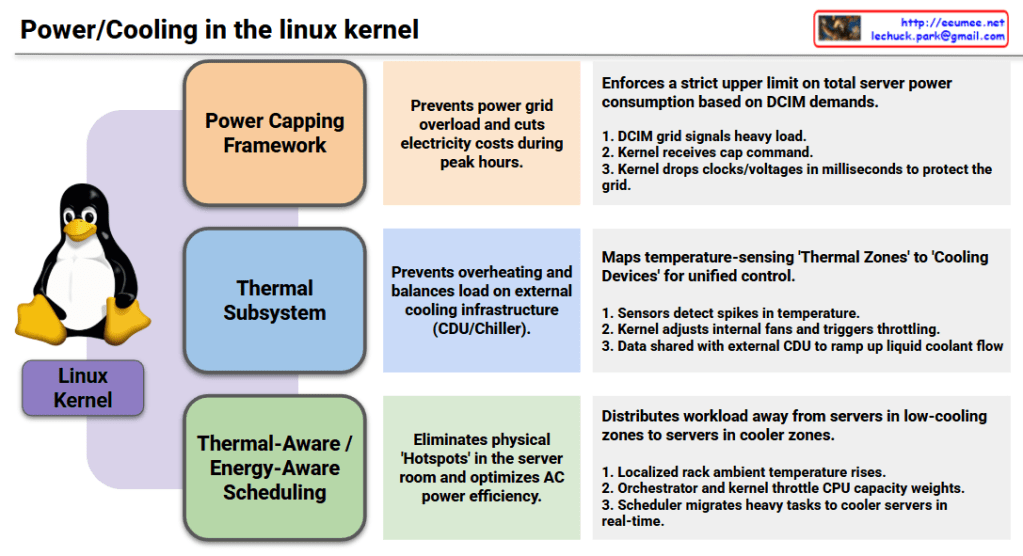
1. Power Capping Framework

  • Objective (Center): Prevents power grid overload and cuts electricity costs during peak hours.
  • Mechanism (Right): Enforces a strict upper limit on total server power consumption based on DCIM (Datacenter Infrastructure Management) demands.
    1. The DCIM grid signals a heavy load status.
    2. The Linux kernel receives the specific power capping command.
    3. The kernel immediately drops processor clocks and voltages in milliseconds to protect the local power grid.

2. Thermal Subsystem

  • Objective (Center): Prevents hardware overheating and balances the load on external cooling infrastructure, such as Coolant Distribution Units (CDUs) and chillers.
  • Mechanism (Right): Maps temperature-sensing ‘Thermal Zones’ directly to hardware ‘Cooling Devices’ for unified, holistic control.
    1. Hardware sensors detect sudden spikes in internal temperature.
    2. The kernel dynamically adjusts internal server fans and triggers safety throttling.
    3. Temperature telemetry data is actively shared with the external datacenter CDU to ramp up liquid coolant flow rates.

3. Thermal-Aware / Energy-Aware Scheduling

  • Objective (Center): Eliminates physical ‘Hotspots’ within the server room layout and optimizes overall air conditioning (AC) power efficiency.
  • Mechanism (Right): Distributes heavy workloads away from physical servers trapped in low-cooling zones to servers located in cooler zones.
    1. The localized ambient temperature around a specific server rack rises.
    2. The datacenter orchestrator and the kernel work together to throttle the target CPU’s capacity weights.
    3. The Linux scheduler automatically migrates heavy compute tasks to cooler servers across the room in real-time.

Modern Linux has evolved beyond managing isolated servers; it now acts as a holistic orchestrator that treats the datacenter’s power grid, liquid cooling loops, and air conditioning as a single, unified organism.

#LinuxKernel #PowerManagement #ThermalSubsystem #EnergyAwareScheduling #DatacenterInfrastructure #DCIM #LiquidCooling #GreenComputing #HPC #InfrastructureAutomation #CloudInfrastructure

With Gemini

Compute Accelerators (accel) subsystem

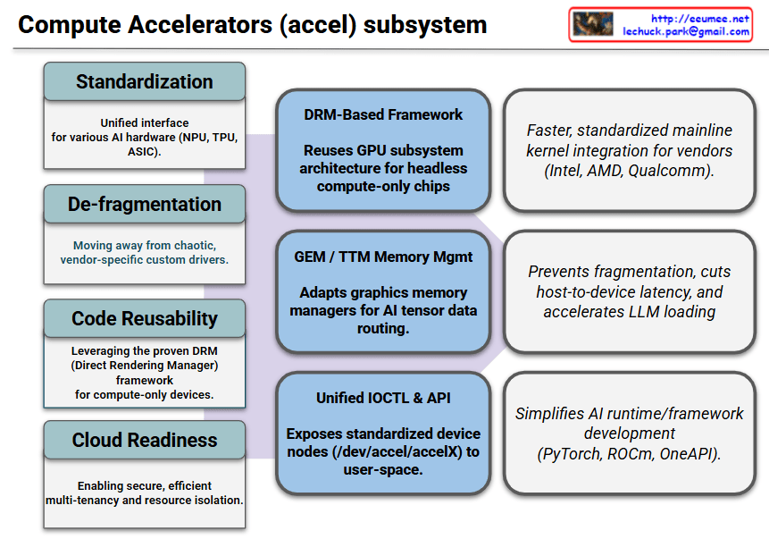
Here is the explanation of the provided diagram, which illustrates the architectural flow of the Linux kernel’s Compute Accelerators (accel) subsystem from its initial goals to its final real-world impacts.

1. Objectives & Background (Left Grey Blocks)

This section defines the systemic issues the accel subsystem was created to solve.

  • Standardization: Establishes a unified, consistent interface across diverse AI hardware types such as NPUs, TPUs, and custom ASICs.
  • De-fragmentation: Eliminates the chaotic era of vendor-specific, closed, or fragmented custom drivers.
  • Code Reusability: Leverages the mature and battle-tested DRM (Direct Rendering Manager) framework specifically tailored for “headless” (compute-only) devices.
  • Cloud Readiness: Lays the foundation for secure, efficient multi-tenancy and robust hardware resource isolation in data centers.

2. Key Features (Center Blue Blocks)

These are the core technical mechanisms implemented inside the Linux kernel to achieve the defined goals.

  • DRM-Based Framework: Reuses the underlying GPU subsystem architecture to manage headless compute chips smoothly within drivers/accel/.
  • GEM / TTM Memory Mgmt: Adapts established graphics memory management technologies (GEM and TTM) to efficiently route massive AI tensor data.
  • Unified IOCTL & API: Exposes standardized device nodes (e.g., /dev/accel/accelX) directly to user-space applications.

3. Real-World Effects & Benefits (Right White Blocks)

This section outlines the concrete performance gains and development advantages delivered to hardware vendors and AI developers.

  • For Hardware Vendors (Intel, AMD, Qualcomm, etc.): Enables faster, highly standardized integration of physical drivers directly into the upstream mainline Linux kernel.
  • For System Performance: Prevents system memory fragmentation, radically slashes host-to-device latency, and accelerates the loading speeds of massive LLM (Large Language Model) weights.
  • For AI Framework Development: Significantly simplifies the engineering efforts required to build and optimize upper-layer AI runtimes and frameworks like PyTorch, AMD ROCm, and Intel OneAPI.

The Linux kernel’s accel subsystem leverages the proven DRM framework and GEM/TTM memory management to standardize diverse AI hardware interfaces, thereby eliminating vendor driver fragmentation, slashing data latency for LLMs, and drastically simplifying cloud multi-tenancy and AI framework development.

#LinuxKernel #AIAccelerator #ComputeAccelerators #NPU #GPU #DRM #KernelArchitecture #OpenSource #PyTorch #LLM #CloudComputing