Distributed Training Optimization : Network Traffic Control (eBPF) – Bottleneck

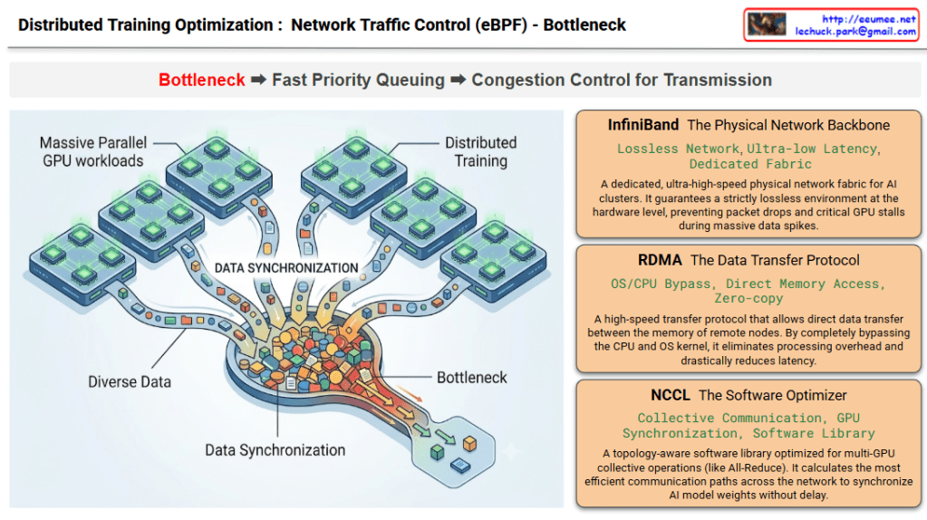
This infographic intuitively visualizes the “Bottleneck” phase—the very first step in network optimization for large-scale AI distributed training environments. It also outlines the three foundational infrastructure technologies involved in this process. As indicated by the red highlight on the word Bottleneck in the top workflow process, this specific diagram is entirely focused on defining the problem area.

1. Visual Context Description (Left Illustration)

  • The graphic on the left depicts a Massive Parallel GPU workloads environment, where numerous GPU clusters are operating simultaneously.
  • “Diverse Data” pouring out from each distinct GPU node converges into a massive, funnel-like channel labeled “DATA SYNCHRONIZATION.”
  • The illustration brilliantly captures a severe “Bottleneck” occurring as a massive volume of data packets (represented by the colorful blocks) attempts to squeeze through this narrow passage all at once, causing a massive traffic jam.

2. Core Infrastructure Technologies (Right Panels) The right side details the three core infrastructure stacks where this physical and logical data synchronization (and the resulting bottleneck) takes place.

  • InfiniBand (The Physical Network Backbone): A dedicated, ultra-high-speed physical network fabric for AI clusters. It guarantees a strictly lossless environment at the hardware level, preventing packet drops and critical GPU stalls during massive data spikes as seen on the left.
  • RDMA (The Data Transfer Protocol): A high-speed transfer protocol that allows direct data transfer between the memory of remote nodes. By completely bypassing the CPU and OS kernel, it eliminates processing overhead and drastically reduces latency.
  • NCCL (The Software Optimizer): A topology-aware software library optimized for multi-GPU collective operations (like All-Reduce). It calculates the most efficient communication paths across the network to synchronize AI model weights without delay.

📝 Summary

This diagram defines the problem state by using a funnel metaphor to visualize the inevitable network bottleneck that occurs when multiple GPUs synchronize data during distributed AI training. Simultaneously, it serves as an introductory technical overview, clearly outlining the keyword-centric roles of the underlying infrastructure stack—InfiniBand, RDMA, and NCCL—that handles this immense traffic.

#AIInfrastructure #DistributedTraining #NetworkBottleneck #DataCenter #InfiniBand #RDMA #NCCL #GPUCluster

With Gemini
Distributed Training Optimization : Network Traffic Control (eBPF)

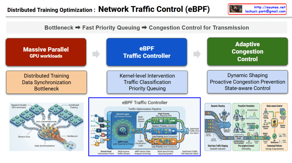
The diagram, titled “Distributed Training Optimization: Network Traffic Control,” outlines a core 3-stage optimization pipeline. It logically unfolds the process of identifying and solving the problem following the top flow path: Bottleneck ➡️ Fast Priority Queuing ➡️ Congestion Control for Transmission.

1. Massive Parallel GPU Workloads

  • Visual Description: The red section on the left and the illustration below it depict “Diverse Data” pouring out from multiple GPU cluster nodes and converging into a single, narrow bottleneck.
  • Core Meaning: It illustrates the Data Synchronization traffic that is essential during the Distributed Training of AI models. It structurally highlights the inevitable network bottleneck that occurs when countless GPUs attempt to exchange computational results simultaneously.

2. eBPF Traffic Controller

  • Visual Description: The central blue section introduces the core control engine designed to resolve the aforementioned bottleneck. The lower illustration shows complex traffic being neatly sorted into three pipes (priority lanes) at the OS Kernel Driver layer.
  • Core Meaning: It demonstrates Kernel-level Intervention, allowing access to network packets without massive overhead. Following the Traffic Classification logic, the system implements Priority Queuing: mission-critical traffic directly affecting training speed (like All-Reduce) is routed to the top ‘High Priority (VIP)’ queue, while standard storage traffic goes to the ‘Low Priority’ queue.

3. Adaptive Congestion Control

  • Visual Description: The green section on the right depicts the dynamic management of queued traffic as it is transmitted into the actual network fabric. The illustration shows eBPF agents adjusting valves in real-time (Dynamic Shaping), predicting and preventing network spikes (Proactive Prevention), and maintaining stable traffic flow based on the overall application context (State-aware Control).
  • Core Meaning: Beyond simple prioritization, it proactively monitors network switch buffer states and overall infrastructure congestion to flexibly adjust transmission rates. Ultimately, this creates a flawless, optimized data flow with zero latency.

📝 Summary

This diagram visualizes the complete pipeline for maximizing communication efficiency in AI data centers. To resolve the inevitable network bottlenecks caused by AI distributed training, it introduces an eBPF-based traffic controller operating at the lowest kernel level to prioritize traffic, and executes adaptive congestion control reflecting real-time network states to ensure seamless data transmission.

#AIDataCenter #eBPF #DistributedTraining #TrafficControl #InfrastructureEngineering #GPUCluster #AIOps #NetworkOptimization

With Gemini

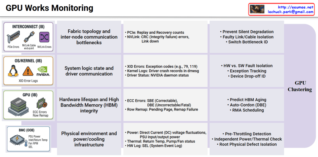
GPU Works Monitoring

1. The Physical Infrastructure Defense Line (BMC / Out-of-Band)

This is the foundational layer that preemptively monitors the physical environmental limits at the chassis level through a microcontroller (BMC), operating completely independently of the OS or kernel state.

  • Technical Significance: High-density GPU systems are highly sensitive to power spikes and cooling degradation. Before the OS triggers GPU throttling to protect the hardware, this layer must catch anomalies like high-voltage distribution fluctuations or rising return temperatures in liquid/air cooling systems via the System Event Log (SEL).
  • Fault Isolation: It narrows down the root cause by isolating purely physical infrastructure factors—such as “insufficient power supply” or “thermal limits”—before any software-level performance analysis begins.

2. The Hardware Integrity Layer (GPU / In-Band)

This layer tracks the physical aging and data corruption of the High Bandwidth Memory (HBM) and compute cores directly at the chip level, utilizing tools like DCGM (Data Center GPU Manager).

  • Technical Significance: While Single Bit Errors (SBE) within the HBM are auto-correctable, their accumulation strongly indicates memory component aging. Conversely, uncorrectable Double Bit Errors (DBE) or Row Remapping failures due to depleted spare memory banks signify an immediate, fatal interruption to the workload.
  • Fault Isolation: These metrics serve as definitive evidence to immediately isolate (cordon/drain) the affected node from the training cluster and initiate a Return Merchandise Authorization (RMA) with the hardware vendor.

3. The System Logic & Driver Layer (OS/Kernel / In-Band)

This is the logical debugging domain that analyzes the communication state between the NVIDIA device drivers and the Linux kernel, primarily tracking dmesg and XID error logs.

  • Technical Significance: It is crucial to clearly distinguish between software-level crashes caused by user applications (e.g., memory leaks, infinite loops, segfaults) and physical communication disconnections where the GPU stops responding and drops off the PCIe bus (Device Drop-off).
  • Fault Isolation: By separating pure user workload bugs from actual physical device communication failures, this layer eliminates time wasted on unnecessary hardware replacements or node reboots.

4. The Interconnect & Fabric Layer (Interconnect / In-Band)

In a scale-out environment extending beyond a single node, this layer monitors the high-speed data highway for communication bottlenecks.

  • Technical Significance: During large-scale distributed training, a single poor PCIe slot connection or an NVLink CRC integrity check failure can drastically plummet the bandwidth of the entire ring topology. These issues do not crash the system or spit out fatal errors, making them the primary culprits of “Silent Performance Degradation.”
  • Fault Isolation: By tracking PCIe Replay and NVLink Recovery counts in real-time, it pinpoints the exact faulty cables, switch ports, or riser cards causing excessive packet retransmissions among thousands of connections.

Architectural Conclusion

Ultimately, when faced with the single symptom of “a specific node’s computation has slowed down,” you can only pinpoint the true root cause by cross-analyzing Redfish API-based Out-of-Band telemetry with DCGM/dmesg-based In-Band telemetry in real-time.

Moving beyond simple monitoring dashboards, integrating these complex telemetry data streams into an LLM and RAG-based automated agent will serve as a powerful tool to drastically reduce MTTR without requiring manual administrator intervention.

#AIDataCenter #GPUCluster #Telemetry #RootCauseAnalysis #BMC #NVIDIA #DCGM #NVLink #AIOps #InfrastructureAsCode #DataCenterManagement

With Gemini

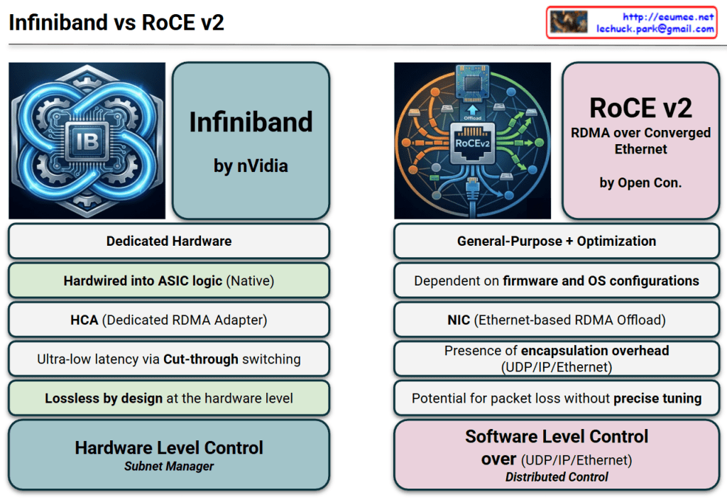
Infiniband vs RoCE v2

This image provides a technical comparison between InfiniBand and RoCE v2 (RDMA over Converged Ethernet), the two dominant networking protocols used in modern AI data centers and High-Performance Computing (HPC) environments.


1. Architectural Philosophy

  • InfiniBand (Dedicated Hardware): Designed from the ground up specifically for high-throughput, low-latency communication. It is a proprietary ecosystem largely driven by NVIDIA (Mellanox).
  • RoCE v2 (General-Purpose + Optimization): An evolution of standard Ethernet designed to bring RDMA (Remote Direct Memory Access) capabilities to traditional network infrastructures. It is backed by the Open Consortium.

2. Hardware vs. Software Logic

  • Hardwired ASIC (InfiniBand): The protocol logic is baked directly into the silicon. This “Native” approach ensures consistent performance with minimal jitter.
  • Firmware & OS Dependent (RoCE v2): Relies more heavily on the NIC’s firmware and operating system configurations, making it more flexible but potentially more complex to stabilize.

3. Data Transfer Efficiency

  • Ultra-low Latency (InfiniBand): Utilizes Cut-through switching, where the switch starts forwarding the packet as soon as the destination address is read, without waiting for the full packet to arrive.
  • Encapsulation Overhead (RoCE v2): Because it runs on Ethernet, it must wrap RDMA data in UDP/IP/Ethernet headers. This adds “overhead” (extra data bits) and processing time compared to the leaner InfiniBand frames.

4. Reliability and Loss Management

  • Lossless by Design (InfiniBand): It uses a credit-based flow control mechanism at the hardware level, ensuring that a sender never transmits data unless the receiver has room to buffer it. This guarantees zero packet loss.
  • Tuning-Dependent (RoCE v2): Ethernet is natively “lossy.” To make RoCE v2 work effectively, the network must be “Converged” using complex features like PFC (Priority Flow Control) and ECN (Explicit Congestion Notification). Without precise tuning, performance can collapse during congestion.

5. Network Management

  • Subnet Manager (InfiniBand): Uses a centralized “Subnet Manager” to discover the topology and manage routing, which simplifies the management of massive GPU clusters.
  • Distributed Control (RoCE v2): Functions like a traditional IP network where routing and control are distributed across the switches and routers.

Comparison Summary

FeatureInfiniBandRoCE v2
Primary DriverPerformance & StabilityCost-effectiveness & Compatibility
ComplexityPlug-and-play (within IB ecosystem)Requires expert-level network tuning
LatencyAbsolute LowestLow (but higher than IB)
ScalabilityHigh (specifically for AI/HPC)High (standard Ethernet scalability)

Design & Logic: InfiniBand is a dedicated, hardware-native solution for ultra-low latency, whereas RoCE v2 adapts general-purpose Ethernet for RDMA through software-defined optimization and firmware.

Efficiency & Reliability: InfiniBand is “lossless by design” with minimal overhead via cut-through switching, while RoCE v2 incurs encapsulation overhead and requires precise network tuning to prevent packet loss.

Control & Management: InfiniBand utilizes centralized hardware-level management (Subnet Manager) for peak stability, while RoCE v2 relies on distributed software-level control over standard UDP/IP/Ethernet stacks.

#InfiniBand #RoCEv2 #RDMA #AIDataCenter #NetworkingArchitecture #NVIDIA #HighPerformanceComputing #GPUCluster #DataCenterDesign #Ethernet #AITraining

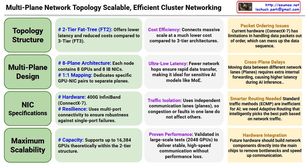
Multi-Plane Network Topology ( deepseek v3)

Multi-Plane Network Topology for Scalable AI Clusters

Core Architecture (Left – Green Sections)

Topology Structure

  • Adopts 2-Tier Fat-Tree (FT2) architecture for reduced latency and cost efficiency compared to 3-Tier
  • Achieves massive scale connections at much lower cost than 3-tier architectures

Multi-Plane Design

  • 8-Plane Architecture: Each node contains 8 GPUs and 8 IB NICs
  • 1:1 Mapping: Dedicates specific GPU-NIC pairs to separate planes

NIC Specifications

  • Hardware: 400G InfiniBand (ConnectX-7)
  • Resilience: Multi-port connectivity ensures robustness against single-port failures

Maximum Scalability

  • Theoretically supports up to 16,384 GPUs within the 2-tier structure

Advantages (Center – Purple Sections)

Cost Efficiency: Connects massive scale at much lower cost compared to 3-tier architectures

Ultra-Low Latency: Fewer network hops ensure rapid data transfer, ideal for latency-sensitive AI models like MoE

Traffic Isolation: Independent communication lanes (planes) prevent congestion or faults in one lane from affecting others

Proven Performance: Validated in large-scale tests with 2048 GPUs, delivering stable and high-speed communication

Challenges (Right – Orange Sections)

Packet Ordering Issues: Current hardware (ConnectX-7) has limitations in handling out-of-order data packets

Cross-Plane Delays: Moving data between different network planes requires extra internal forwarding, causing higher latency during AI inference

Smarter Routing Needed: Standard traffic methods (ECMP) are inefficient for AI; requires Adaptive Routing that intelligently selects the best path based on network traffic

Hardware Integration: Future hardware should build network components directly into main chips to remove bottlenecks and speed up communication


Summary

This document presents a multi-plane network topology using 2-tier Fat-Tree architecture that scales AI clusters up to 16,384 GPUs cost-effectively with ultra-low latency. The 8-plane design with 1:1 GPU-NIC mapping provides traffic isolation and resilience, though challenges remain in packet ordering and cross-plane communication. Future improvements require smarter routing algorithms and deeper hardware-network integration to optimize AI workload performance.

#AIInfrastructure #DataCenterNetworking #HPC #InfiniBand #GPUCluster #NetworkTopology #FatTree #ScalableComputing #MLOps #AIHardware #DistributedComputing #CloudInfrastructure #NetworkArchitecture #DeepLearning #AIatScale

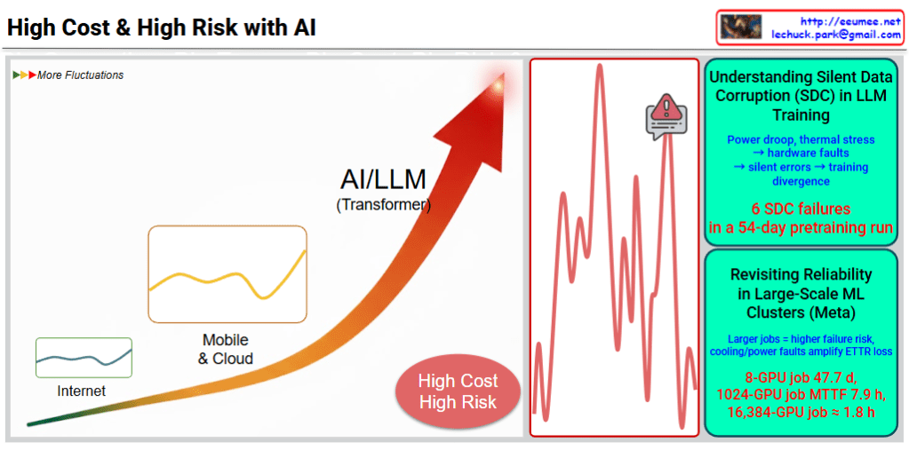
High Cost & High Risk with AI

This image illustrates the high cost and high risk of AI/LLM (Large Language Model) training.

Key Analysis

Left: AI/LLM Growth Path

  • Evolution from Internet → Mobile & Cloud → AI/LLM (Transformer)
  • Each stage shows increasing fluctuations in the graph
  • Emphasizes “High Cost, High Risk” message

Center: Real Problem Visualization

The red graph shows dramatic performance spikes that occurred during actual training processes.

Top Right: Silent Data Corruption (SDC) Issues

Silent data corruption from hardware failures:

  • Power drops, thermal stress → hardware faults
  • Silent errors → training divergence
  • 6 SDC failures in a 54-day pretraining run

Bottom Right: Reliability Issues in Large-Scale ML Clusters (Meta Case)

Real failure cases:

  • 8-GPU job: average 47.7 days
  • 1024-GPU job: MTTF (Mean Time To Failure) 7.9 hours
  • 16,384-GPU job: failure in approximately 1.8 hours

Summary

  1. As GPU scale increases, failure probability rises exponentially, making large-scale AI training extremely costly and technically risky.
  2. Hardware-induced silent data corruption causes training divergence, with 6 failures recorded in just 54 days of pretraining.
  3. Meta’s experience shows massive GPU clusters can fail in under 2 hours, highlighting infrastructure reliability as a critical challenge.

#AITraining #LLM #MachineLearning #DataCorruption #GPUCluster #MLOps #AIInfrastructure #HardwareReliability #TransformerModels #HighPerformanceComputing #AIRisk #MLEngineering #DeepLearning

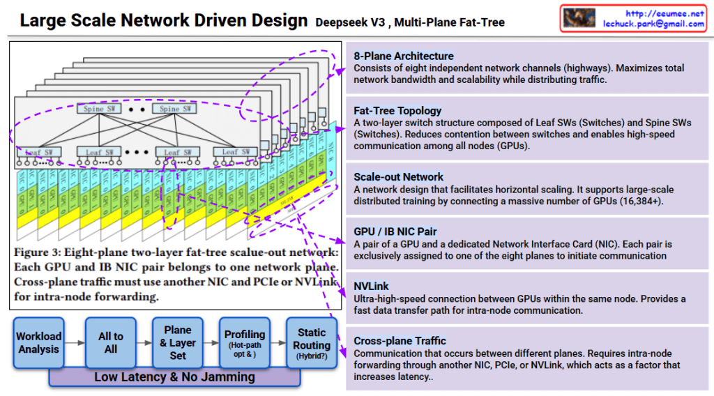
Large Scale Network Driven Design ( Deepseek V3)

Deepseek v3 Large-Scale Network Architecture Analysis

This image explains the Multi-Plane Fat-Tree network structure of Deepseek v3.

Core Architecture

1. 8-Plane Architecture

  • Consists of eight independent network channels (highways)
  • Maximizes network bandwidth and distributes traffic for enhanced scalability

2. Fat-Tree Topology

  • Two-layer switch structure:
    • Leaf SW (Leaf Switches): Directly connected to GPUs
    • Spine SW (Spine Switches): Interconnect leaf switches
  • Enables high-speed communication among all nodes (GPUs) while minimizing switch contention

3. GPU/IB NIC Pair

  • Each GPU is paired with a dedicated Network Interface Card (NIC)
  • Each pair is exclusively assigned to one of the eight planes to initiate communication

Communication Methods

NVLink

  • Ultra-high-speed connection between GPUs within the same node
  • Fast data transfer path used for intra-node communication

Cross-plane Traffic

  • Occurs when communication happens between different planes
  • Requires intra-node forwarding through another NIC, PCIe, or NVLink
  • Primary factor that increases latency

Network Optimization Process

The workflow below minimizes latency and prevents network congestion:

  1. Workload Analysis
  2. All to All (analyzing all-to-all communication patterns)
  3. Plane & Layer Set (plane and layer assignment)
  4. Profiling (Hot-path opt K) (hot-path optimization)
  5. Static Routing (Hybrid) (hybrid static routing approach)

Goal: Low latency & no jamming

Scalability

This design is a scale-out network for large-scale distributed training supporting 16,384+ GPUs. Each plane operates independently to maximize overall system throughput.


3-Line Summary

Deepseek v3 uses an 8-plane fat-tree network architecture that connects 16,384+ GPUs through independent communication channels, minimizing contention and maximizing bandwidth. The two-layer switch topology (Spine and Leaf) combined with dedicated GPU-NIC pairs enables efficient traffic distribution across planes. Cross-plane traffic management and hot-path optimization ensure low-latency, high-throughput communication for large-scale AI training.

#DeepseekV3 #FatTreeNetwork #MultiPlane #NetworkArchitecture #ScaleOut #DistributedTraining #AIInfrastructure #GPUCluster #HighPerformanceComputing #NVLink #DataCenterNetworking #LargeScaleAI

With Claude