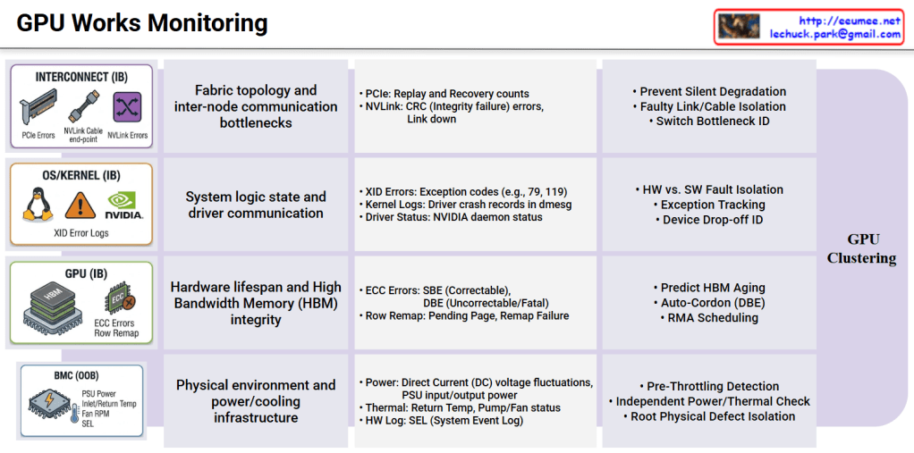
GPU Works Monitoring

1. The Physical Infrastructure Defense Line (BMC / Out-of-Band)

This is the foundational layer that preemptively monitors the physical environmental limits at the chassis level through a microcontroller (BMC), operating completely independently of the OS or kernel state.

  • Technical Significance: High-density GPU systems are highly sensitive to power spikes and cooling degradation. Before the OS triggers GPU throttling to protect the hardware, this layer must catch anomalies like high-voltage distribution fluctuations or rising return temperatures in liquid/air cooling systems via the System Event Log (SEL).
  • Fault Isolation: It narrows down the root cause by isolating purely physical infrastructure factors—such as “insufficient power supply” or “thermal limits”—before any software-level performance analysis begins.

2. The Hardware Integrity Layer (GPU / In-Band)

This layer tracks the physical aging and data corruption of the High Bandwidth Memory (HBM) and compute cores directly at the chip level, utilizing tools like DCGM (Data Center GPU Manager).

  • Technical Significance: While Single Bit Errors (SBE) within the HBM are auto-correctable, their accumulation strongly indicates memory component aging. Conversely, uncorrectable Double Bit Errors (DBE) or Row Remapping failures due to depleted spare memory banks signify an immediate, fatal interruption to the workload.
  • Fault Isolation: These metrics serve as definitive evidence to immediately isolate (cordon/drain) the affected node from the training cluster and initiate a Return Merchandise Authorization (RMA) with the hardware vendor.

3. The System Logic & Driver Layer (OS/Kernel / In-Band)

This is the logical debugging domain that analyzes the communication state between the NVIDIA device drivers and the Linux kernel, primarily tracking dmesg and XID error logs.

  • Technical Significance: It is crucial to clearly distinguish between software-level crashes caused by user applications (e.g., memory leaks, infinite loops, segfaults) and physical communication disconnections where the GPU stops responding and drops off the PCIe bus (Device Drop-off).
  • Fault Isolation: By separating pure user workload bugs from actual physical device communication failures, this layer eliminates time wasted on unnecessary hardware replacements or node reboots.

4. The Interconnect & Fabric Layer (Interconnect / In-Band)

In a scale-out environment extending beyond a single node, this layer monitors the high-speed data highway for communication bottlenecks.

  • Technical Significance: During large-scale distributed training, a single poor PCIe slot connection or an NVLink CRC integrity check failure can drastically plummet the bandwidth of the entire ring topology. These issues do not crash the system or spit out fatal errors, making them the primary culprits of “Silent Performance Degradation.”
  • Fault Isolation: By tracking PCIe Replay and NVLink Recovery counts in real-time, it pinpoints the exact faulty cables, switch ports, or riser cards causing excessive packet retransmissions among thousands of connections.

Architectural Conclusion

Ultimately, when faced with the single symptom of “a specific node’s computation has slowed down,” you can only pinpoint the true root cause by cross-analyzing Redfish API-based Out-of-Band telemetry with DCGM/dmesg-based In-Band telemetry in real-time.

Moving beyond simple monitoring dashboards, integrating these complex telemetry data streams into an LLM and RAG-based automated agent will serve as a powerful tool to drastically reduce MTTR without requiring manual administrator intervention.

#AIDataCenter #GPUCluster #Telemetry #RootCauseAnalysis #BMC #NVIDIA #DCGM #NVLink #AIOps #InfrastructureAsCode #DataCenterManagement

With Gemini
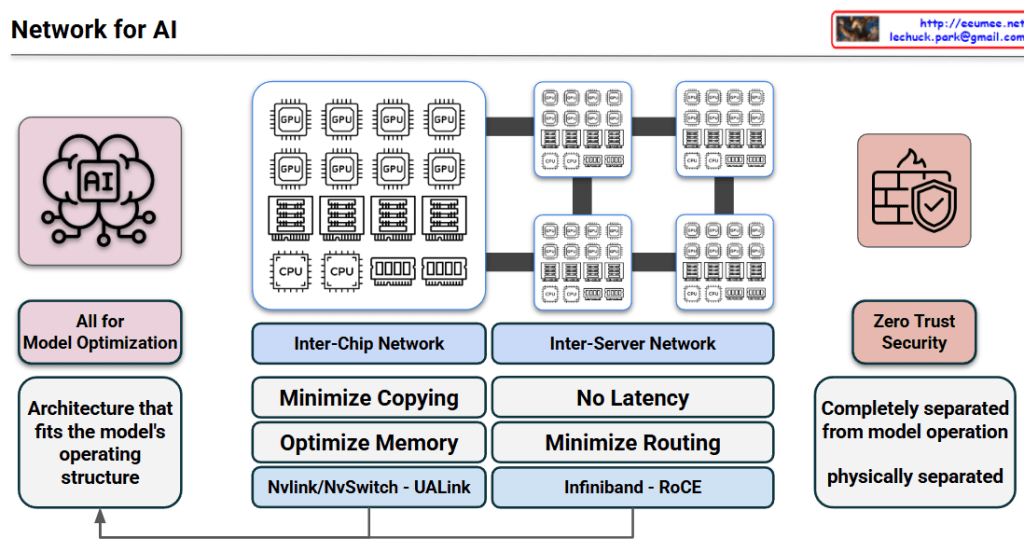
Network for AI

1. Core Philosophy: All for Model Optimization

The primary goal is to create an “Architecture that fits the model’s operating structure.” Unlike traditional general-purpose data centers, AI infrastructure is specialized to handle the massive data throughput and synchronized computations required by LLMs (Large Language Models).

2. Hierarchical Network Design

The architecture is divided into two critical layers to handle different levels of data exchange:

A. Inter-Chip Network (Scale-Up)

This layer focuses on the communication between individual GPUs/Accelerators within a single server or node.

  • Key Goals: Minimize data copying and optimize memory utilization (Shared Memory/Memory Pooling).
  • Technologies: * NVLink / NVSwitch: NVIDIA’s proprietary high-speed interconnect.
  • UALink (Ultra Accelerator Link): The new open standard designed for scale-up AI clusters.

B. Inter-Server Network (Scale-Out)

This layer connects multiple server nodes to form a massive AI cluster.

  • Key Goals: Achieve “No Latency” (Ultra-low latency) and minimize routing overhead to prevent bottlenecks during collective communications (e.g., All-Reduce).
  • Technologies: * InfiniBand: A lossless, high-bandwidth fabric preferred for its low CPU overhead.
  • RoCE (RDMA over Converged Ethernet): High-speed Ethernet that allows direct memory access between servers.

3. Zero Trust Security & Physical Separation

A unique aspect of this architecture is the treatment of security.

  • Operational Isolation: The security and management plane is completely separated from the model operation plane.
  • Performance Integrity: By being physically separated, security protocols (like firewalls or encryption inspection) do not introduce latency into the high-speed compute fabric where the model runs. This ensures that a “Zero Trust” posture does not degrade training or inference speed.

4. Architectural Feedback Loop

The arrow at the bottom indicates a feedback loop: the performance metrics and requirements of the inter-chip and inter-server networks directly inform the ongoing optimization of the overall architecture. This ensures the platform evolves alongside advancing AI model structures.


The architecture prioritizes model-centric optimization, ensuring infrastructure is purpose-built to match the specific operating requirements of large-scale AI workloads.

It employs a dual-tier network strategy using Inter-chip (NVLink/UALink) for memory efficiency and Inter-server (InfiniBand/RoCE) for ultra-low latency cluster scaling.

Zero Trust security is integrated through complete physical separation from the compute fabric, allowing for robust protection without causing any performance bottlenecks.

#AIDC #ArtificialIntelligence #GPU #Networking #NVLink #UALink #InfiniBand #RoCEv2 #ZeroTrust #DataCenterArchitecture #MachineLearningOps #ScaleOut

Interconnection Driven Design (Deepseek v3)

Interconnection Driven Design

This image outlines a technical approach to solving bottlenecks in High-Performance Computing (HPC) and AI/LLM infrastructure. It is categorized into three main rows, each progressing from a Problem to a Solution, and finally to a hardware-level Final Optimization.

1. Convergence of Scale-Up and Scale-Out

Focuses on resolving inefficiencies between server communication and GPU computation.

  • Problem (IB Communication): The speed of inter-server connections (e.g., InfiniBand) creates a bottleneck for total system performance.
  • Inefficiency (Streaming Multiprocessor): The GPU’s core computational units (SMs) waste resources handling network overhead instead of focusing on actual calculations.
  • Solution (SM Offload): Communication tasks are delegated (offloaded) to dedicated coprocessors, allowing SMs to focus exclusively on computation.
  • Final Optimization (Unified Network Adapter): Physically integrating intra-node and inter-node communication into a single Network Interface Card (NIC) to minimize data movement paths.

2. Bandwidth Contention & Latency

Addresses the limitations of data bandwidth and processing delays.

  • Problem (KV Cache): Reusable token data for LLM inference frequently travels between the CPU and GPU, consuming significant bandwidth.
  • Bottleneck (PCIe): The primary interconnect has limited bandwidth, leading to contention and performance degradation during traffic spikes.
  • Solution (Traffic Class – TC): A prioritization mechanism (QoS) ensures urgent, latency-sensitive traffic is processed before less critical data.
  • Final Optimization (I/O Die Chiplet Integration): Integrating network I/O directly alongside the GPU die bypasses PCIe entirely, eliminating contention and drastically reducing latency.

3. Node-Limited Routing

Optimizes data routing strategies for distributed neural networks.

  • Key Tech (NVLink): A high-speed, intra-node GPU interconnect strategically used to maximize local data transfer.
  • Context (Experts): Neural network modules (MoE – Mixture of Experts) are distributed across various nodes, requiring activation for specific tokens.
  • Solution/Strategy (Minimize IB Cost): Reducing overhead by restricting slow inter-node usage (InfiniBand) to a single hop while distributing data internally via fast NVLink.
  • Final Optimization (Node-Limited): Algorithms restrict the selection of “Experts” (modules) to a limited node group, reducing inter-node traffic and guaranteeing communication efficiency.

Summary

  1. Integration: The design overcomes system bottlenecks by physically unifying network adapters and integrating I/O dies directly with GPUs to bypass slow connections like PCIe.
  2. Offloading & Prioritization: It improves efficiency by offloading network tasks from GPU cores (SMs) and prioritizing urgent traffic (Traffic Class) to reduce latency.
  3. Routing Optimization: It utilizes “Node-Limited” routing strategies to maximize high-speed local connections (NVLink) and minimize slower inter-server communication in distributed AI models.

#InterconnectionDrivenDesign #AIInfrastructure #GPUOptimization #HPC #ChipletIntegration #NVLink #LatencyReduction #LLMHardware #infiniband

With Gemini

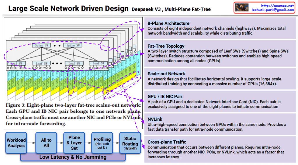
Large Scale Network Driven Design ( Deepseek V3)

Deepseek v3 Large-Scale Network Architecture Analysis

This image explains the Multi-Plane Fat-Tree network structure of Deepseek v3.

Core Architecture

1. 8-Plane Architecture

  • Consists of eight independent network channels (highways)
  • Maximizes network bandwidth and distributes traffic for enhanced scalability

2. Fat-Tree Topology

  • Two-layer switch structure:
    • Leaf SW (Leaf Switches): Directly connected to GPUs
    • Spine SW (Spine Switches): Interconnect leaf switches
  • Enables high-speed communication among all nodes (GPUs) while minimizing switch contention

3. GPU/IB NIC Pair

  • Each GPU is paired with a dedicated Network Interface Card (NIC)
  • Each pair is exclusively assigned to one of the eight planes to initiate communication

Communication Methods

NVLink

  • Ultra-high-speed connection between GPUs within the same node
  • Fast data transfer path used for intra-node communication

Cross-plane Traffic

  • Occurs when communication happens between different planes
  • Requires intra-node forwarding through another NIC, PCIe, or NVLink
  • Primary factor that increases latency

Network Optimization Process

The workflow below minimizes latency and prevents network congestion:

  1. Workload Analysis
  2. All to All (analyzing all-to-all communication patterns)
  3. Plane & Layer Set (plane and layer assignment)
  4. Profiling (Hot-path opt K) (hot-path optimization)
  5. Static Routing (Hybrid) (hybrid static routing approach)

Goal: Low latency & no jamming

Scalability

This design is a scale-out network for large-scale distributed training supporting 16,384+ GPUs. Each plane operates independently to maximize overall system throughput.


3-Line Summary

Deepseek v3 uses an 8-plane fat-tree network architecture that connects 16,384+ GPUs through independent communication channels, minimizing contention and maximizing bandwidth. The two-layer switch topology (Spine and Leaf) combined with dedicated GPU-NIC pairs enables efficient traffic distribution across planes. Cross-plane traffic management and hot-path optimization ensure low-latency, high-throughput communication for large-scale AI training.

#DeepseekV3 #FatTreeNetwork #MultiPlane #NetworkArchitecture #ScaleOut #DistributedTraining #AIInfrastructure #GPUCluster #HighPerformanceComputing #NVLink #DataCenterNetworking #LargeScaleAI

With Claude

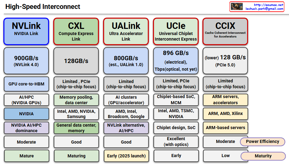
High-Speed Interconnect

This image compares five major high-speed interconnect technologies:

NVLink (NVIDIA Link)

  • Speed: 900GB/s (NVLink 4.0)
  • Use Case: GPU core-to-HBM, AI/HPC with NVIDIA GPUs
  • Features: NVIDIA proprietary, dominates AI/HPC market
  • Maturity: Mature

CXL (Compute Express Link)

  • Speed: 128GB/s
  • Use Case: Memory pooling, data center, general data center memory
  • Features: Supported by Intel, AMD, NVIDIA, Samsung; PCIe-based with chip-to-chip focus
  • Maturity: Maturing

UALink (Ultra Accelerator Link)

  • Speed: 800GB/s (estimated, UALink 1.0)
  • Use Case: AI clusters, GPU/accelerator interconnect
  • Features: Led by AMD, Intel, Broadcom, Google; NVLink alternative
  • Maturity: Early (2025 launch)

UCIe (Universal Chiplet Interconnect Express)

  • Speed: 896GB/s (electrical), 7Tbps (optical, not yet available)
  • Use Case: Chiplet-based SoC, MCM (Multi-Chip Module)
  • Features: Supported by Intel, AMD, TSMC, NVIDIA; chiplet design focus
  • Maturity: Early stage, excellent performance with optical version

CCIX (Cache Coherent Interconnect for Accelerators)

  • Speed: 128GB/s (PCIe 5.0-based)
  • Use Case: ARM servers, accelerators
  • Features: Supported by ARM, AMD, Xilinx; ARM-based server focus
  • Maturity: Low, limited power efficiency

Summary: All technologies are converging toward higher bandwidth, lower latency, and chip-to-chip connectivity to address the growing demands of AI/HPC workloads. The effectiveness varies by ecosystem, with specialized solutions like NVLink leading in performance while universal standards like CXL focus on broader compatibility and adoption.

With Claude

NVLink, Infiniband

This diagram compares two GPU networking technologies: NVLink and InfiniBand, both essential for parallel computing expansion.

On the left side, the “NVLink” section shows multiple GPUs connected vertically through purple interconnect bars. This represents the “Scale UP” approach, where GPUs are vertically scaled within a single system for tight integration.

On the right side, the “InfiniBand” section demonstrates how multiple server nodes connect through an InfiniBand network. This illustrates the “Scale Out” approach, where computing power expands horizontally across multiple independent systems.

Both technologies share the common goal of expanding parallel processing capabilities, but they do so in different architectural approaches. NVLink focuses on high-speed, direct connections between GPUs in a single system, while InfiniBand specializes in networking across multiple systems to support distributed computing environments.

The optimization of these expansion configurations is crucial for maximizing performance in high-performance computing, AI training, and other compute-intensive applications. System architects must carefully consider workload characteristics, data movement patterns, and scaling requirements when choosing between these technologies or determining how to best implement them together in hybrid configurations.

With Claude

Network for GPUs

with a Claude’s Help
The network architecture demonstrates 3 levels of connectivity technologies:

  1. NVLink (Single node Parallel processing)
  • Technology for directly connecting GPUs within a single node
  • Supports up to 256 GPU connections
  • Physical HBM (High Bandwidth Memory) sharing
  • Optimized for high-performance GPU parallel processing within individual servers
  1. NVSwitch
  • Switching technology that extends NVLink limitations
  • Provides logical HBM sharing
  • Key component for large-scale AI model operations
  • Enables complete mesh network configuration between GPU groups
  • Efficiently connects multiple GPU groups within One Box Server
  • Targets large AI model workloads
  1. InfiniBand
  • Network technology for server clustering
  • Supports RDMA (Remote Direct Memory Access)
  • Used for distributed computing and HPC (High Performance Computing) tasks
  • Implements hierarchical network topology
  • Enables large-scale cluster configuration across multiple servers
  • Focuses on distributed and HPC workloads

This 3-tier architecture provides scalability through:

  • GPU parallel processing within a single server (NVLink)
  • High-performance connectivity between GPU groups within a server (NVSwitch)
  • Cluster configuration between multiple servers (InfiniBand)

The architecture enables efficient handling of various workload scales, from small GPU tasks to large-scale distributed computing. It’s particularly effective for maximizing GPU resource utilization in large-scale AI model training and HPC workloads.

Key Benefits:

  • Hierarchical scaling from single node to multi-server clusters
  • Efficient memory sharing through both physical and logical HBM
  • Flexible topology options for different computing needs
  • Optimized for both AI and high-performance computing workloads
  • Comprehensive solution for GPU-based distributed computing

This structure provides a complete solution from single-server GPU operations to complex distributed computing environments, making it suitable for a wide range of high-performance computing needs.