’26 OCP Korea Techday https://ocpkorea.com/
#OCPKoreaTechDay #OCP #OpenComputerProject #DataCenter #OCPKorea #OpenSourece #TechConference #AIDataCenter
The Computing for the Fair Human Life.
’26 OCP Korea Techday https://ocpkorea.com/
#OCPKoreaTechDay #OCP #OpenComputerProject #DataCenter #OCPKorea #OpenSourece #TechConference #AIDataCenter
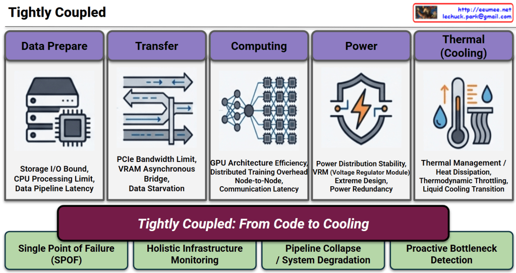
1. The 5 Pillars & Potential Bottlenecks (Top Section)
Data Prepare ➔ Transfer ➔ Computing ➔ Power ➔ Thermal (Cooling).2. The Core Message (Center Section)
3. Strategic Implications & Solutions (Bottom Section)
#AIDataCenter #TightlyCoupled #InfrastructureMonitoring #ProactiveOperations #DataCenterArchitecture #AIInfrastructure #Power #Computing #Cooling #Data #IO #Memory
With Gemini
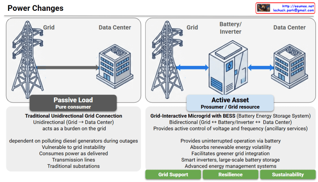
Power Architecture Evolution: From Passive Load to Active Asset
This diagram illustrates the critical evolution of data center power systems, highlighting the shift from a traditional “Passive Load” model to an “Active Asset” model. This transition is emerging as an essential power architecture and strategic direction for future AI Data Centers (AI DCs), which demand massive energy consumption and absolute operational stability.
1. AS-IS: Passive Load (Pure Consumer)
2. TO-BE: Active Asset (Prosumer / Grid Resource)
Conclusion: An Indispensable Power Direction for AI DCs
Rather than simply acting as facilities that drain massive amounts of electricity, modern data centers must evolve into grid-interactive assets. Given the exponential surge in power demands and the strict continuous operation requirements of AI workloads, adopting this “Active Asset” architecture with BESS and smart inverters is no longer just an eco-friendly alternative—it is an essential and inevitable power infrastructure direction for the successful deployment and scaling of AI Data Centers.
#AIDC #AIDataCenter #DataCenterInfrastructure #ESS #Inverter #GridInteractive
With Gemini
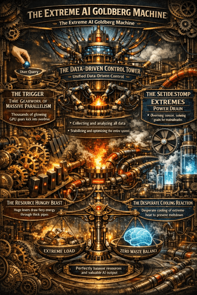
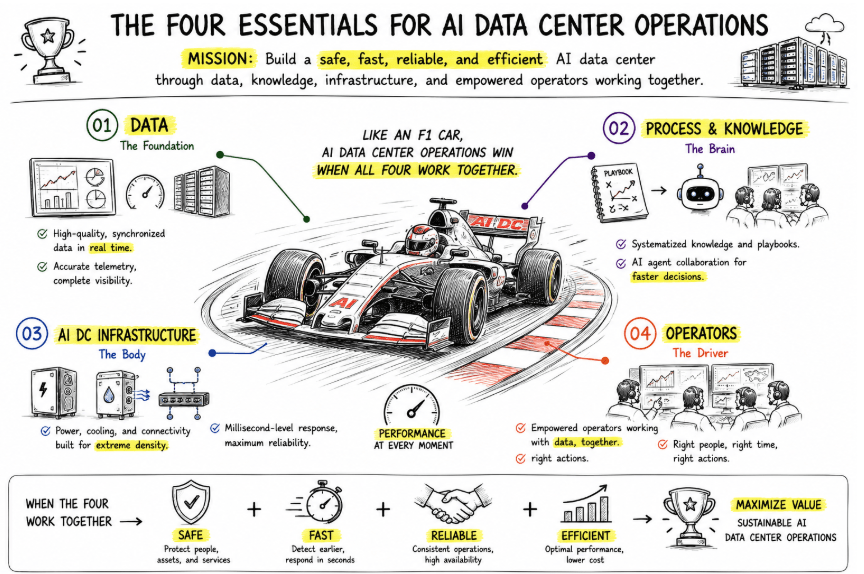
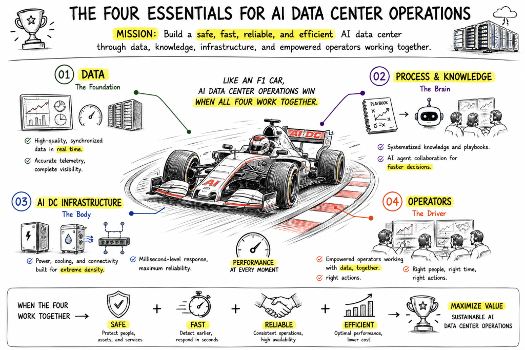
A single AI response triggers a massive chain reaction of compute, power, and cooling.
Only unified, data-driven control can stabilize this fragile system and eliminate waste.
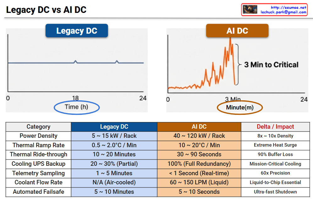
This infographic illustrates the radical shift in operational paradigms between Legacy Data Centers and AI Data Centers, highlighting the transition from “Human-Speed” steady-state management to “Machine-Speed” real-time automation.
| Category | Legacy DC | AI DC | Delta / Impact |
| Power Density | 5 ~ 15 kW / Rack | 40 ~ 120 kW / Rack | 8x ~ 10x Density |
| Thermal Ramp Rate | 0.5 ~ 2.0°C / Min | 10 ~ 20°C / Min | Extreme Heat Surge |
| Thermal Ride-through | 10 ~ 20 Minutes | 30 ~ 90 Seconds | 90% Buffer Loss |
| Cooling UPS Backup | 20 ~ 30% (Partial) | 100% (Full Redundancy) | Mission-Critical Cooling |
| Telemetry Sampling | 1 ~ 5 Minutes | < 1 Second (Real-time) | 60x Precision |
| Coolant Flow Rate | N/A (Air-cooled) | 60 ~ 150 LPM (Liquid) | Liquid-to-Chip Essential |
| Automated Failsafe | 5 ~ 10 Minutes | 5 ~ 10 Seconds | Ultra-fast Shutdown |
With rack densities reaching 120 kW, air cooling is no longer viable. The shift to Liquid-to-Chip cooling with flow rates up to 150 LPM is mandatory to manage the 10–20°C per minute thermal ramp rates.
In a Legacy DC, operators have a 20-minute “Golden Hour” to respond to cooling failures. In an AI DC, this buffer collapses to seconds, making sub-second telemetry and automated failsafe protocols the only way to prevent hardware damage.
#AIDataCenter #AIOps #LiquidCooling #InfrastructureOptimization #DataCenterDesign #HighDensityComputing #ThermalManagement #DigitalTransformation
With Gemini

This diagram illustrates how data centers are transforming as they enter the AI era.
The top section shows major technology revolutions and their timelines:
Conventional data centers consisted of the following core components:
These were designed as relatively independent layers.
With the introduction of AI (especially LLMs), data centers require specialized infrastructure:
The circular connection in the center of the diagram represents the most critical feature of AI data centers:
Unlike traditional data centers, in AI data centers:
These elements must be closely integrated in design, and optimizing just one element cannot guarantee overall system performance.
AI workloads require moving beyond the traditional layer-by-layer independent design approach of conventional data centers, demanding that computing-network-power-cooling be designed as one integrated system. This demonstrates that a holistic approach is essential when building AI data centers.
AI data centers fundamentally differ from traditional data centers through the tight integration of computing, networking, power, and cooling systems. GPU-based AI workloads create unprecedented power density and heat generation, requiring liquid cooling and HVDC power systems. Success in AI infrastructure demands holistic design where all components are co-optimized rather than independently engineered.
#AIDataCenter #DataCenterEvolution #GPUInfrastructure #LiquidCooling #AIComputing #LLM #DataCenterDesign #HighPerformanceComputing #AIInfrastructure #HVDC #HolisticDesign #CloudComputing #DataCenterCooling #AIWorkloads #FutureOfDataCenters
With Claude

