ESS + Supercapacitor: Coordination

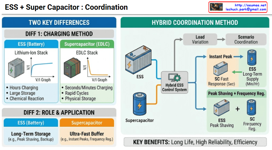
This infographic serves as a technical resource comparing the characteristics of Energy Storage Systems (ESS) and Supercapacitors, and explaining how a ‘Hybrid Coordination Method’ that combines these two technologies operates. The chart is primarily divided into ‘Two Key Differences’ on the left and ‘Hybrid Coordination Method’ on the right.

1. Left Section: Two Key Differences

This section highlights the fundamental technical distinctions between the two storage devices.

  • Diff 1: Charging Method
    • ESS (Battery): Utilizes a Lithium-Ion Stack. It stores energy via a Chemical Reaction, so as shown in the V/I graph, voltage and current rise gradually, taking hours for a full charge. However, it excels at large storage.
    • Supercapacitor (EDLC): Utilizes an EDLC (Electric Double-Layer Capacitor) Stack. It uses a Physical Storage method to store charge, resulting in a very steep rise in voltage and current in the graph, with charging complete in seconds or minutes. It can withstand repeated rapid cycles.
  • Diff 2: Role & Application
    • ESS (Battery): Functions as a long-term storage device. For example, it is used for Peak Shaving to reduce load during high-demand periods or as a backup power source.
    • Supercapacitor: Functions as an ultra-fast buffer. It is deployed where immediate and powerful responses are required, such as responding to instant peaks in power demand or for power grid Frequency Regulation.

2. Right Section: Hybrid Coordination Method

This section demonstrates how the two devices work together when combined into a single system.

  • System Configuration: The central ‘Hybrid ESS Control System’ is the brain. This controller detects external ‘Load Variation’ and executes the appropriate ‘Scenario Coordination’. The system consists of a blue, battery-shaped ESS unit and a blue, cylindrical Supercapacitor unit.
  • Coordination Scenario 1: Instant Peak
    • When an instant peak occurs (a sudden surge in load), the controller first commands the fast-responding Supercapacitor (SC) to provide a fast response in seconds, absorbing the initial power shock.
    • Subsequently, the controller hands over power supply to the ESS, which provides long-term supply in minutes or hours. This prevents rapid battery discharge and ensures the stability of the overall power supply.
  • Coordination Scenario 2: Peak Shaving + Frequency Reg.
    • The two devices simultaneously perform different roles to stabilize the power grid.
    • The ESS is responsible for peak shaving, reducing large and sustained load peaks.
    • Simultaneously, the Supercapacitor handles fine-tuned frequency regulation, adjusting for small, rapid frequency fluctuations. This combination of “ESS + SC” addresses both needs.

3. Bottom Section: Key Benefits

The major advantages achieved through this hybrid coordination are:

  • Long Life: By having the Supercapacitor absorb initial power shocks, the stress on the battery is reduced, thereby extending its lifespan.
  • High Reliability: Leveraging the strengths of both devices allows for a stable and reliable response to various power grid changes.
  • Efficiency: Each device takes on the role it does best, resulting in higher overall energy management efficiency for the system.

Summary: This infographic compares ESS (Batteries), which excel at bulk storage but have slower response times, with Supercapacitors, which have smaller storage capacity but offer ultra-fast response times. It explains a coordinated operation method that combines these two devices using a hybrid control system to effectively address both instantaneous power peaks and sustained energy demands. This combined approach achieves the key benefits of long life, high reliability, and efficiency.

#ESS #Supercapacitor #EnergyStorageSystem #HybridEnergySystem #GridStabilization #PeakShaving #FrequencyRegulation #EnergyTech #Infographic #EcoTech

With Gemini
Data Center Power

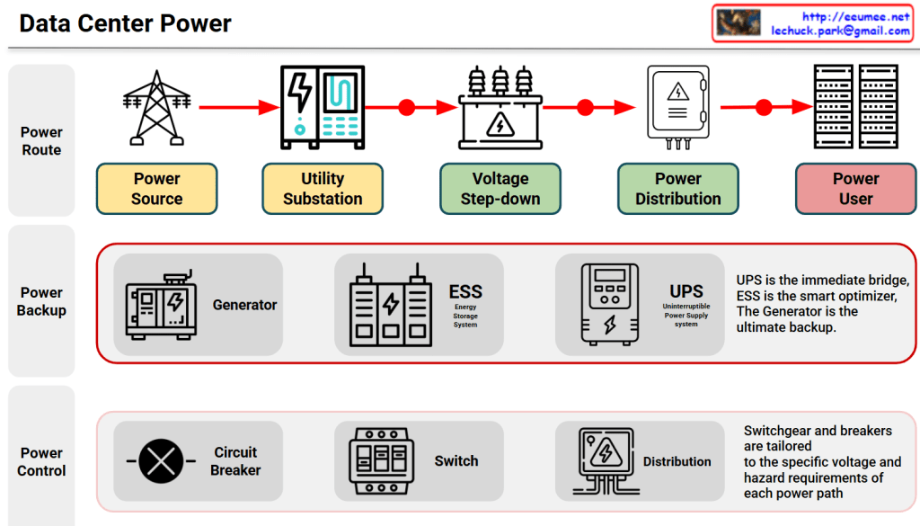
This diagram, provides a comprehensive and easy-to-understand overview of a Data Center Power Architecture. It breaks down the complex electrical infrastructure into three main functional layers: Power Route, Power Backup, and Power Control.

1. Power Route (The Main Flow of Electricity)

This top layer illustrates the journey of electricity from the grid all the way to the servers.

  • Power Source: This is the starting point where high-voltage electricity is delivered from the external power grid or power plants.
  • Utility Substation: The high-voltage power first enters the data center’s dedicated substation to be safely received and managed.
  • Voltage Step-down: Because grid voltage is way too high for servers, heavy-duty transformers step down the voltage to a lower, safer operating level.
  • Power Distribution: The stepped-down electricity is split and routed into various distribution switchboards and panels.
  • Power User: The final destination. Clean, stable power is delivered directly to the high-density IT racks and servers.

2. Power Backup (The Safety Net)

This layer ensures the data center remains fully operational even during severe grid failures or blackouts. It highlights three critical components:

  • Generator: The ultimate powerhouse for long-term survival. It takes a few seconds to start up but can supply continuous power for days during extended outages.
  • ESS (Energy Storage System): The smart optimizer. It strategically saves energy when power is cheap and discharges it during peak demand to cut costs and improve efficiency.
  • UPS (Uninterruptible Power Supply): The zero-second shield. It provides instant battery power the exact millisecond a blackout occurs so that servers never drop a single packet.

Key Concept: “UPS is the immediate bridge, ESS is the smart optimizer, and the Generator is the ultimate backup.”

3. Power Control (The Guard and Router)

The bottom layer focuses on the safety and granular control of the electricity flowing through the system.

  • Circuit Breaker: Automatically cuts off the electrical flow instantly if a short circuit or overload is detected, protecting expensive equipment from catching fire.
  • Switch: Allows operators to manually or automatically redirect power paths for maintenance or load balancing.
  • Distribution: Fine-tunes and splits the power safely down to the individual hardware level.

Key Concept: “Switchgear and breakers are tailored to the specific voltage and hazard requirements of each power path.”

📝 In Summary

The architecture shown how a modern data center achieves maximum uptime. Power Route brings the electricity in, Power Backup ensures it never goes dark, and Power Control guarantees that the entire flow remains safe, stable, and highly optimized.

#DataCenter #AIDC #PowerInfrastructure #UPS #ESS #BackupGenerator #ElectricalEngineering #Switchgear #DataCenterDesign

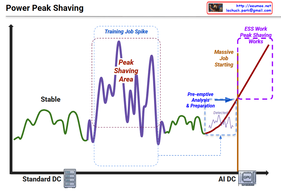
Peak Shaving with Data

Graph Interpretation: Power Peak Shaving in AI Data Centers

This graph illustrates the shift in power consumption patterns from traditional data centers to AI-driven data centers and the necessity of “Peak Shaving” strategies.

1. Standard DC (Green Line – Left)

  • Characteristics: Shows “Stable” power consumption.
  • Interpretation: Traditional server workloads are relatively predictable with low volatility. The power demand stays within a consistent range.

2. Training Job Spike (Purple Line – Middle)

  • Characteristics: Significant fluctuations labeled “Peak Shaving Area.”
  • Interpretation: During AI model training, power demand becomes highly volatile. The spikes (peaks) and valleys represent the intensive GPU cycles required during training phases.

3. AI DC & Massive Job Starting (Red Line – Right)

  • Characteristics: A sharp, vertical-like surge in power usage.
  • Interpretation: As massive AI jobs (LLM training, etc.) start, the power load skyrockets. The graph shows a “Pre-emptive Analysis & Preparation” phase where the system detects the surge before it hits the maximum threshold.

4. ESS Work & Peak Shaving (Purple Dotted Box – Top Right)

  • The Strategy: To handle the “Massive Job Starting,” the system utilizes ESS (Energy Storage Systems).
  • Action: Instead of drawing all power from the main grid (which could cause instability or high costs), the ESS discharges stored energy to “shave” the peak, smoothing out the demand and ensuring the AI DC operates safely.

Summary

  1. Volatility Shift: AI workloads (GPU-intensive) create much more extreme and unpredictable power spikes compared to standard data center operations.
  2. Proactive Management: Modern AI Data Centers require pre-emptive detection and analysis to prepare for sudden surges in energy demand.
  3. ESS Integration: Energy Storage Systems (ESS) are critical for “Peak Shaving,” providing the necessary power buffer to maintain grid stability and cost efficiency.

#DataCenter #AI #PeakShaving #EnergyStorage #ESS #GPU #PowerManagement #SmartGrid #TechInfrastructure #AIDC #EnergyEfficiency

with Gemini

Peak Shaving


“Power – Peak Shaving” Strategy

The image illustrates a 5-step process for a ‘Peak Shaving’ strategy designed to maximize power efficiency in data centers. Peak shaving is a technique used to reduce electrical load during periods of maximum demand (peak times) to save on electricity costs and ensure grid stability.

1. IT Load & ESS SoC Monitoring

This is the data collection and monitoring phase to understand the current state of the system.

  • Grid Power: Monitoring the maximum power usage from the external power grid.
  • ESS SoC/SoH: Checking the State of Charge (SoC) and State of Health (SoH) of the Energy Storage System (ESS).
  • IT Load (PDU): Measuring the actual load through Power Distribution Units (PDUs) at the server rack level.
  • LLM/GPU Workload: Monitoring the real-time workload of AI models (LLM) and GPUs.

2. ML-based Peak Prediction

Predicting future power demand based on the collected data.

  • Integrated Monitoring: Consolidating data from across the entire infrastructure.
  • Machine Learning Optimization: Utilizing AI algorithms to accurately predict when power peaks will occur and preparing proactive responses.

3. Peak Shaving Via PCS (Power Conversion System)

Utilizing physical energy storage hardware to distribute the power load.

  • Pre-emptive Analysis & Preparation: Determining the “Time to Charge.” The system charges the batteries when electricity rates are low.
  • ESS DC Power: During peak times, the stored Direct Current (DC) in the ESS is converted to Alternating Current (AC) via the PCS to supplement the power supply, thereby reducing reliance on the external grid.

4. Job Relocation (K8s/Slurm)

Adjusting the scheduling of IT tasks based on power availability.

  • Scheduler Decision Engine: Activated when a peak time is detected or when ESS battery levels are low.
  • Job Control: Lower priority jobs are queued or paused, and compute speeds are throttled (power suppressed) to minimize consumption.

5. Parameter & Model Optimization

The most advanced stage, where the efficiency of the AI models themselves is optimized.

  • Real-time Batch Size Adjustment: Controlling throughput to prevent sudden power spikes.
  • Large Model -> sLLM (Lightweight): Transitioning to smaller, lightweight Large Language Models (sLLM) to reduce GPU power consumption without service downtime.

Summary

The core message of this diagram is that High-Quality/High-Resolution Data is the foundation for effective power management. By combining hardware solutions (ESS/PCS), software scheduling (K8s/Slurm), and AI model optimization (sLLM), a data center can significantly reduce operating expenses (OPEX) and ultimately increase profitability (Make money) through intelligent peak shaving.


#AI_DC #PowerControl #DataCenter #EnergyEfficiency #PeakShaving #GreenIT #MachineLearning #ESS #AIInfrastructure #GPUOptimization #Sustainability #TechInnovation

UPS & ESS


UPS vs. ESS & Key Safety Technologies

This image illustrates the structural differences between UPS (Uninterruptible Power System) and ESS (Energy Storage System), emphasizing the advanced safety technologies required for ESS due to its “High Power, High Risk” nature.

1. Left Side: System Comparison (UPS vs. ESS)

This section contrasts the purpose and scale of the two systems, highlighting why ESS requires stricter safety measures.

  • UPS (Traditional System)
    • Purpose: Bridges the power gap for a short duration (10–30 mins) until the backup generator starts (Generator Wake-Up Time).
    • Scale: Relatively low capacity (25–500 kWh) and output (100 kW – N MW).
  • ESS (High-Capacity System)
    • Purpose: Stores energy for long durations (4+ hours) for active grid management, such as Peak Shaving.
    • Scale: Handles massive power (~100+ MW) and capacity (~400+ MWh).
    • Risk Factor: Labeled as “High Power, High Risk,” indicating that the sheer energy density makes it significantly more hazardous than UPS.

2. Right Side: 4 Key Safety Technologies for ESS

Since standard UPS technologies (indicated in gray text) are insufficient for ESS, the image outlines four critical technological upgrades (indicated in bold text).

① Battery Management System (BMS)

  • (From) Simple voltage monitoring and cut-off.
  • [To] Active Balancing & Precise State Estimation: Requires algorithms that actively balance cell voltages and accurately calculate SOC (State of Charge) and SOH (State of Health).

② Thermal Management System

  • (From) Simple air cooling or fans.
  • [To] Forced Air (HVAC) / Liquid Cooling: Due to high heat generation, robust air conditioning (HVAC) or direct Liquid Cooling systems are necessary.

③ Fire Detection & Suppression

  • (From) Detecting smoke after a fire starts.
  • [To] Off-gas Detection & Dedicated Suppression: Detects Off-gas (released before thermal runaway) to prevent fires early, using specialized suppressants like Clean Agents or Water Mist.

④ Physical/Structural Safety

  • (From) Standard metal enclosures.
  • [To] Explosion-proof & Venting Design: Enclosures must withstand explosions and safely vent gases.
  • [To] Fire Propagation Prevention: Includes fire barriers and BPU (Battery Protective Units) to stop fire from spreading between modules.

Summary

  • Scale: ESS handles significantly higher power and capacity (>400 MWh) compared to UPS, serving long-term grid needs rather than short-term backup.
  • Risk: Due to the “High Power, High Risk” nature of ESS, standard safety measures used in UPS are insufficient.
  • Solution: Advanced technologies—such as Liquid Cooling, Off-gas Detection, and Active Balancing BMS—are mandatory to ensure safety and prevent thermal runaway.

#ESS #UPS #BatterySafety #BMS #ThermalManagement #EnergyStorage #FireSafety #Engineering #TechTrends #OffGasDetection

WIth Gemini

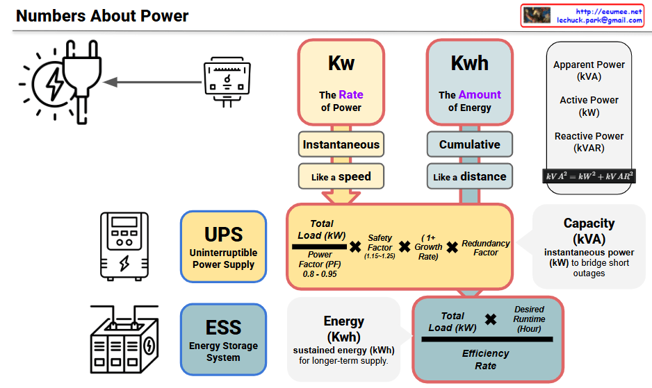
Numbers about power

kW (Instantaneous Power) ↔ UPS (Uninterruptible Power Supply)

UPS Core Objective: Instantaneous Power Supply Capability

  • kW represents the power needed “right now at this moment”
  • UPS priority is immediate power supply during outages
  • Like the “speed” concept in the image, UPS focuses on instantaneous power delivery speed
  • Design actual kW capacity considering Power Factor (PF) 0.8-0.95
  • Calculate total load (kW) reflecting safety factor, growth rate, and redundancy

kWh (Energy Capacity) ↔ ESS (Energy Storage System)

ESS Core Objective: Sustained Energy Supply Capability

  • kWh indicates “how long” power can be supplied
  • ESS priority is long-term stable power supply
  • Like the “distance” concept in the image, ESS focuses on power supply duration
  • Required ESS capacity = Total Load (kW) × Desired Runtime (Hours)
  • Design actual storage capacity considering efficiency rate

Complementary Operation Strategy

Phase 1: UPS Immediate Response

  • Power outage → UPS immediately supplies power in kW units
  • Short-term power supply for minutes to tens of minutes

Phase 2: ESS Long-term Support

  • Extended outages → ESS provides sustained power in kWh units
  • Long-term power supply for hours to days

Summary: This structure optimally matches kW (instantaneousness) with UPS strengths and kWh (sustainability) with ESS capabilities. UPS handles immediate power needs while ESS ensures long-duration supply, creating a comprehensive power backup solution.

With Claude

Power Control : UPS vs ESS

ESS System Analysis for AI Datacenter Power Control

This diagram illustrates the ESS (Energy Storage System) technology essential for providing flexible high-power supply for AI datacenters. Goldman Sachs Research forecasts that AI will drive a 165% increase in datacenter power demand by 2030, with AI representing about 19% of datacenter power demand by 2028, necessitating advanced power management beyond traditional UPS limitations.

ESS System Features for AI Datacenter Applications

1. High Power Density Battery System

  • Rapid Charge/Discharge: Immediate response to sudden power fluctuations in AI workloads
  • Large-Scale Storage: Massive power backup capacity for GPU-intensive AI processing
  • High Power Density: Optimized for space-constrained datacenter environments

2. Intelligent Power Management Capabilities

  • Overload Management: Handles instantaneous high-power demands during AI inference/training
  • GPU Load Prediction: Analyzes AI model execution patterns to forecast power requirements
  • High Response Speed: Millisecond-level power injection/conversion preventing AI processing interruptions
  • Predictive Analytics: Machine learning-based power demand forecasting

3. Flexible Operation Optimization

  • Peak Shaving: Reduces power costs during AI workload peak hours
  • Load Balancing: Distributes power loads across multiple AI model executions
  • Renewable Energy Integration: Supports sustainable AI datacenter operations
  • Cost Optimization: Minimizes AI operational expenses through intelligent power management

Central Power Management System – Essential Core Component of ESS

The Central Power Management System is not merely an auxiliary feature but a critical essential component of ESS for AI datacenters:

1. Precise Data Collection

  • Real-time monitoring of power consumption patterns by AI workload type
  • Tracking power usage across GPU, CPU, memory, and other components
  • Integration of environmental conditions and cooling system power data
  • Comprehensive telemetry from all datacenter infrastructure elements

2. AI-Based Predictive Analysis

  • Machine learning algorithms for AI workload prediction
  • Power demand pattern learning and optimization
  • Predictive maintenance for failure prevention
  • Dynamic resource allocation based on anticipated needs

3. Fast Automated Logic

  • Real-time automated power distribution control
  • Priority-based power allocation during emergency situations
  • Coordinated control across multiple ESS systems
  • Autonomous decision-making for optimal power efficiency

ESS Advantages over UPS for AI Datacenter Applications

While traditional UPS systems are limited to simple backup power during outages, ESS is specifically designed for the complex and dynamic power requirements of AI datacenters:

Proactive vs. Reactive

  • UPS: Reactive response to power failures
  • ESS: Proactive management of power demands before issues occur

Intelligence Integration

  • UPS: Basic power switching functionality
  • ESS: AI-driven predictive analytics and automated optimization

Scalability and Flexibility

  • UPS: Fixed capacity backup power
  • ESS: Dynamic scaling to handle AI servers that use up to 10 times the power of standard servers

Operational Optimization

  • UPS: Emergency power supply only
  • ESS: Continuous power optimization, cost reduction, and efficiency improvement

This advanced ESS approach is critical as datacenter capacity has grown 50-60% quarter over quarter since Q1 2023, requiring sophisticated power management solutions that can adapt to the unprecedented energy demands of modern AI infrastructure.

Future-Ready Infrastructure

ESS represents the evolution from traditional backup power to intelligent energy management, essential for supporting the next generation of AI datacenters that demand both reliability and efficiency at massive scale.

With Cluade