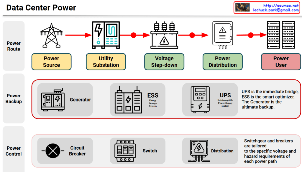
This diagram, provides a comprehensive and easy-to-understand overview of a Data Center Power Architecture. It breaks down the complex electrical infrastructure into three main functional layers: Power Route, Power Backup, and Power Control.
1. Power Route (The Main Flow of Electricity)
This top layer illustrates the journey of electricity from the grid all the way to the servers.
- Power Source: This is the starting point where high-voltage electricity is delivered from the external power grid or power plants.
- Utility Substation: The high-voltage power first enters the data center’s dedicated substation to be safely received and managed.
- Voltage Step-down: Because grid voltage is way too high for servers, heavy-duty transformers step down the voltage to a lower, safer operating level.
- Power Distribution: The stepped-down electricity is split and routed into various distribution switchboards and panels.
- Power User: The final destination. Clean, stable power is delivered directly to the high-density IT racks and servers.
2. Power Backup (The Safety Net)
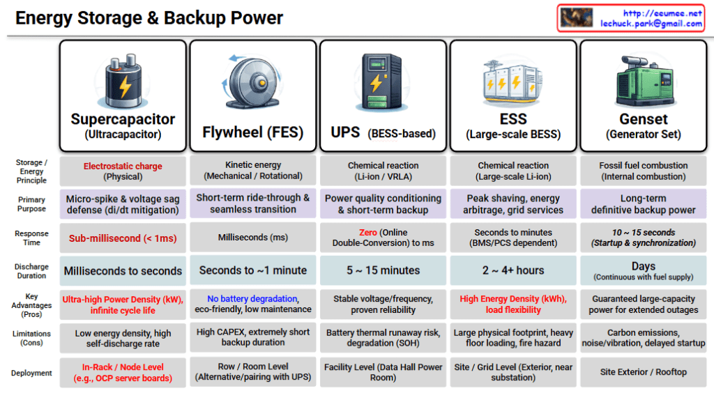
This layer ensures the data center remains fully operational even during severe grid failures or blackouts. It highlights three critical components:
- Generator: The ultimate powerhouse for long-term survival. It takes a few seconds to start up but can supply continuous power for days during extended outages.
- ESS (Energy Storage System): The smart optimizer. It strategically saves energy when power is cheap and discharges it during peak demand to cut costs and improve efficiency.
- UPS (Uninterruptible Power Supply): The zero-second shield. It provides instant battery power the exact millisecond a blackout occurs so that servers never drop a single packet.
Key Concept: “UPS is the immediate bridge, ESS is the smart optimizer, and the Generator is the ultimate backup.”
3. Power Control (The Guard and Router)
The bottom layer focuses on the safety and granular control of the electricity flowing through the system.
- Circuit Breaker: Automatically cuts off the electrical flow instantly if a short circuit or overload is detected, protecting expensive equipment from catching fire.
- Switch: Allows operators to manually or automatically redirect power paths for maintenance or load balancing.
- Distribution: Fine-tunes and splits the power safely down to the individual hardware level.
Key Concept: “Switchgear and breakers are tailored to the specific voltage and hazard requirements of each power path.”
📝 In Summary
The architecture shown how a modern data center achieves maximum uptime. Power Route brings the electricity in, Power Backup ensures it never goes dark, and Power Control guarantees that the entire flow remains safe, stable, and highly optimized.
#DataCenter #AIDC #PowerInfrastructure #UPS #ESS #BackupGenerator #ElectricalEngineering #Switchgear #DataCenterDesign