Distributed Training Optimization : Network Traffic Control (eBPF) – Bottleneck

This infographic intuitively visualizes the “Bottleneck” phase—the very first step in network optimization for large-scale AI distributed training environments. It also outlines the three foundational infrastructure technologies involved in this process. As indicated by the red highlight on the word Bottleneck in the top workflow process, this specific diagram is entirely focused on defining the problem area.

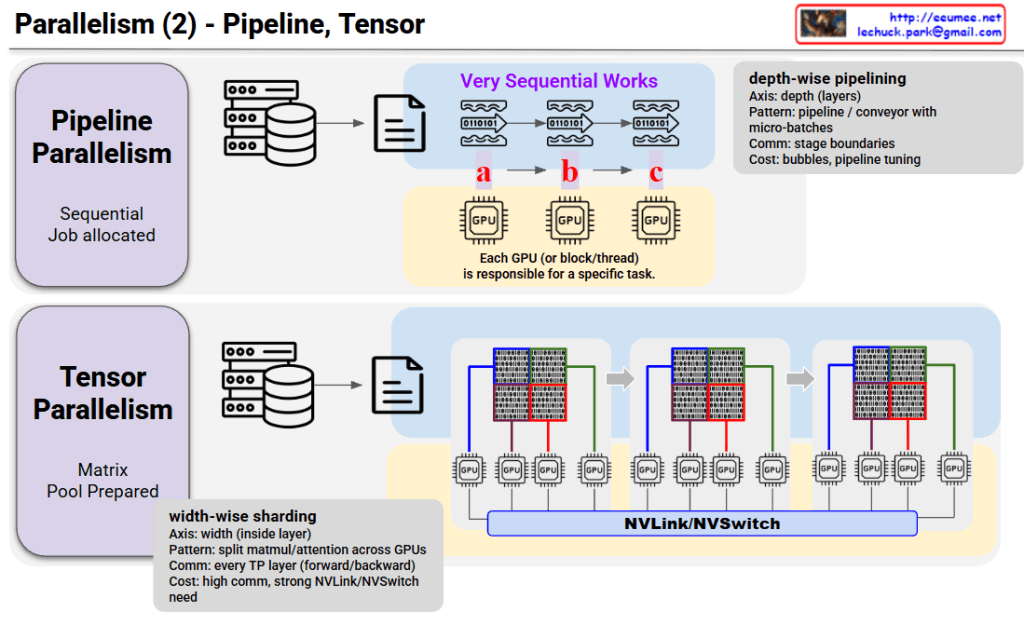
1. Visual Context Description (Left Illustration)

  • The graphic on the left depicts a Massive Parallel GPU workloads environment, where numerous GPU clusters are operating simultaneously.
  • “Diverse Data” pouring out from each distinct GPU node converges into a massive, funnel-like channel labeled “DATA SYNCHRONIZATION.”
  • The illustration brilliantly captures a severe “Bottleneck” occurring as a massive volume of data packets (represented by the colorful blocks) attempts to squeeze through this narrow passage all at once, causing a massive traffic jam.

2. Core Infrastructure Technologies (Right Panels) The right side details the three core infrastructure stacks where this physical and logical data synchronization (and the resulting bottleneck) takes place.

  • InfiniBand (The Physical Network Backbone): A dedicated, ultra-high-speed physical network fabric for AI clusters. It guarantees a strictly lossless environment at the hardware level, preventing packet drops and critical GPU stalls during massive data spikes as seen on the left.
  • RDMA (The Data Transfer Protocol): A high-speed transfer protocol that allows direct data transfer between the memory of remote nodes. By completely bypassing the CPU and OS kernel, it eliminates processing overhead and drastically reduces latency.
  • NCCL (The Software Optimizer): A topology-aware software library optimized for multi-GPU collective operations (like All-Reduce). It calculates the most efficient communication paths across the network to synchronize AI model weights without delay.

📝 Summary

This diagram defines the problem state by using a funnel metaphor to visualize the inevitable network bottleneck that occurs when multiple GPUs synchronize data during distributed AI training. Simultaneously, it serves as an introductory technical overview, clearly outlining the keyword-centric roles of the underlying infrastructure stack—InfiniBand, RDMA, and NCCL—that handles this immense traffic.

#AIInfrastructure #DistributedTraining #NetworkBottleneck #DataCenter #InfiniBand #RDMA #NCCL #GPUCluster

With Gemini
Distributed Training Optimization : Network Traffic Control (eBPF)

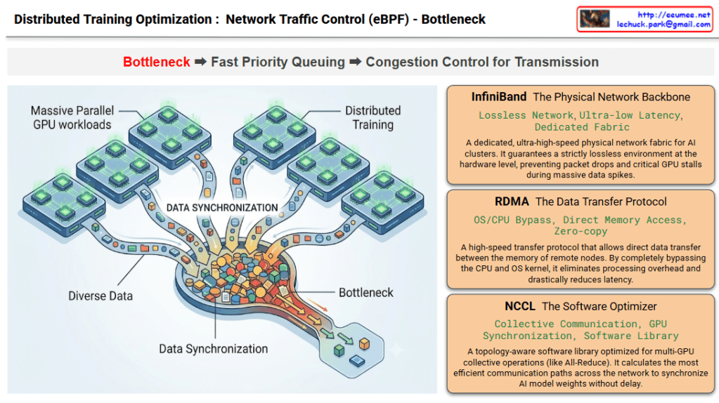
The diagram, titled “Distributed Training Optimization: Network Traffic Control,” outlines a core 3-stage optimization pipeline. It logically unfolds the process of identifying and solving the problem following the top flow path: Bottleneck ➡️ Fast Priority Queuing ➡️ Congestion Control for Transmission.

1. Massive Parallel GPU Workloads

  • Visual Description: The red section on the left and the illustration below it depict “Diverse Data” pouring out from multiple GPU cluster nodes and converging into a single, narrow bottleneck.
  • Core Meaning: It illustrates the Data Synchronization traffic that is essential during the Distributed Training of AI models. It structurally highlights the inevitable network bottleneck that occurs when countless GPUs attempt to exchange computational results simultaneously.

2. eBPF Traffic Controller

  • Visual Description: The central blue section introduces the core control engine designed to resolve the aforementioned bottleneck. The lower illustration shows complex traffic being neatly sorted into three pipes (priority lanes) at the OS Kernel Driver layer.
  • Core Meaning: It demonstrates Kernel-level Intervention, allowing access to network packets without massive overhead. Following the Traffic Classification logic, the system implements Priority Queuing: mission-critical traffic directly affecting training speed (like All-Reduce) is routed to the top ‘High Priority (VIP)’ queue, while standard storage traffic goes to the ‘Low Priority’ queue.

3. Adaptive Congestion Control

  • Visual Description: The green section on the right depicts the dynamic management of queued traffic as it is transmitted into the actual network fabric. The illustration shows eBPF agents adjusting valves in real-time (Dynamic Shaping), predicting and preventing network spikes (Proactive Prevention), and maintaining stable traffic flow based on the overall application context (State-aware Control).
  • Core Meaning: Beyond simple prioritization, it proactively monitors network switch buffer states and overall infrastructure congestion to flexibly adjust transmission rates. Ultimately, this creates a flawless, optimized data flow with zero latency.

📝 Summary

This diagram visualizes the complete pipeline for maximizing communication efficiency in AI data centers. To resolve the inevitable network bottlenecks caused by AI distributed training, it introduces an eBPF-based traffic controller operating at the lowest kernel level to prioritize traffic, and executes adaptive congestion control reflecting real-time network states to ensure seamless data transmission.

#AIDataCenter #eBPF #DistributedTraining #TrafficControl #InfrastructureEngineering #GPUCluster #AIOps #NetworkOptimization

With Gemini

Parallelism (2) – Pipeline, Tensor

Parallelism (2) – Pipeline vs Tensor Parallelism

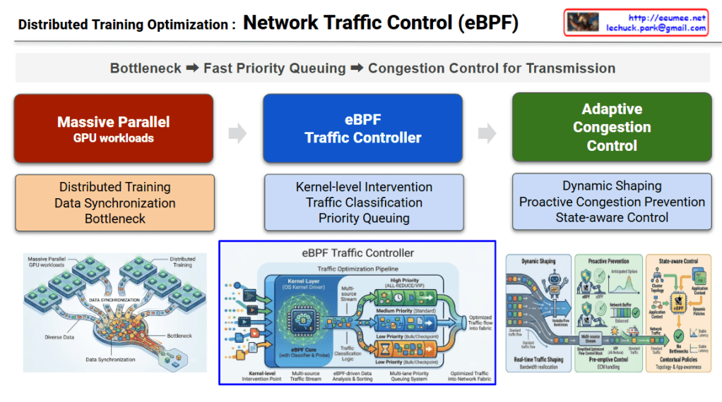
This image compares two parallel processing techniques: Pipeline Parallelism and Tensor Parallelism.

Pipeline Parallelism

Core Concept:

  • Sequential work is divided into multiple stages
  • Each GPU is responsible for a specific task (a → b → c)

Characteristics:

  • Axis: Depth-wise – splits by layers
  • Pattern: Pipeline/conveyor belt with micro-batches
  • Communication: Only at stage boundaries
  • Cost: Bubbles (idle time), requires pipeline tuning

How it works: Data flows sequentially like waves, with each GPU processing its assigned stage before passing to the next GPU.


Tensor Parallelism

Core Concept:

  • Matrix pool is prepared and split in advance
  • All GPUs simultaneously process different parts of the same data

Characteristics:

  • Axis: Width-wise – splits inside layers
  • Pattern: Width-wise sharding – splits matrix/attention across GPUs
  • Communication: Occurs at every Transformer layer (forward/backward)
  • Cost: High communication overhead, requires strong NVLink/NVSwitch

How it works: Large matrices are divided into chunks, with each GPU processing simultaneously while continuously communicating via NVLink/NVSwitch.


Key Differences

AspectPipelineTensor
Split MethodLayer-wise (vertical)Within-layer (horizontal)
GPU RoleDifferent tasksParts of same task
CommunicationLow (stage boundaries)High (every layer)
Hardware NeedsStandardHigh-speed interconnect required

Summary

Pipeline Parallelism splits models vertically by layers with sequential processing and low communication cost, while Tensor Parallelism splits horizontally within layers for parallel processing but requires high-speed interconnects. These two techniques are often combined in training large-scale AI models to maximize efficiency.

#ParallelComputing #DistributedTraining #DeepLearning #GPUOptimization #MachineLearning #ModelParallelism #AIInfrastructure #NeuralNetworks #ScalableAI #HPC

With Claude