Sensors for AI DC Rack

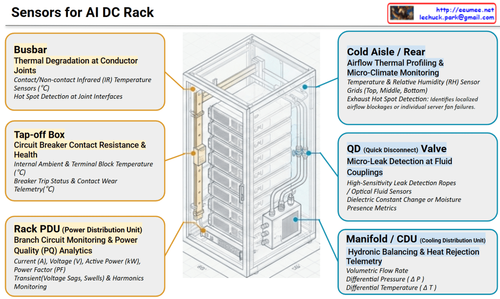
Architecture Walkthrough: High-Density AI Rack Monitoring Topology

This diagram illustrates a comprehensive monitoring framework tailored for next-generation, high-density AI Data Centers. As rack power densities scale upward of 40kW to over 100kW, the integration of high-density power delivery and advanced liquid cooling demands a unified telemetry layer. The architecture symmetrically bifurcates these critical operations into two primary domains: Power Distribution & Electrical Infrastructure (left, in yellow) and Liquid Cooling & Thermal Management (right, in blue).

1. Power Infrastructure Telemetry (Left Domain)

  • Busbar (Top Left): Focuses on tracking surface temperatures at copper/aluminum busway joints using contact or non-contact infrared (IR) sensors. This mitigates the risk of thermal runaway caused by mechanical loosening or joint degradation.
  • Tap-off Box (Middle Left): Monitors the critical junction where power is tapped from the main busway to individual racks. Telemetry captures internal ambient temperatures and circuit breaker contact wear to prevent nuisance tripping under heavy GPU loads.
  • Rack PDU (Bottom Left): Delivers granular power quality (PQ) analytics. Beyond basic billing metrics, it utilizes high-speed sampling to capture transient events—such as voltage sags, swells, and total harmonic distortion (THD)—triggered by sudden LLM training state transitions.

2. Liquid Cooling & Thermal Management (Right Domain)

  • Cold Aisle / Rear (Top Right): Provides 3D micro-climate profiling of the rack enclosure. Using sensor grids (top, middle, bottom), it tracks cold air intake and maps exhaust air behavior to instantaneously flag localized hot spots or individual server fan failures.
  • QD (Quick Disconnect) Valve (Middle Right): Positions high-sensitivity leak detection ropes or optical fluid sensors directly at the fluid mating interfaces of individual GPU server blades. This safeguards expensive IT assets against coolant escape.
  • Manifold / CDU (Bottom Right): Serves as the central hydronic balancing hub. By cross-referencing volumetric flow rate (LPM), differential pressure (Delta P), and differential temperature ($\Delta T$) across supply and return lines, the system continuously calculates the exact real-time heat rejection load in kW.

Executive Summary: The Imperative of High-Fidelity Infrastructure Telemetry

In a modern AI Data Center, the sheer density of accelerated computing clusters renders traditional, coarse facility monitoring completely obsolete. To ensure maximum uptime and operational efficiency, telemetry must undergo a paradigm shift governed by two critical vectors:

1. High Precision & High Resolution

Because GPU workloads scale from idle to maximum power in microseconds, sensors must feature ultra-high sampling rates (millisecond-level resolution for electrical transients) and high precision (milli-degree sensitivity for liquid thermal loops). Coarse, averaged data masks dangerous micro-spikes that degrade hardware components over time. High-resolution telemetry is the baseline requirement for capturing the true, unvarnished physical state of the infrastructure.

2. From Phenomena to Precursors (Omens)

Traditional data center monitoring is reactive—it alerts operators to a phenomenon (e.g., “Rack temperature has exceeded $85^\circ\text{C}$”), which usually means the failure has already occurred.

Conversely, high-fidelity, continuous data allows an AIOps engine to identify precursors or omens—the microscopic anomalies that precede a disaster. For instance:

  • A fractional, steady rise in busbar temperature relative to a static workload implies micro-vibration joint loosening (Thermal Degradation Precursor).
  • A subtle drift in the dielectric constant near a fluid coupling signals a microscopic weep before it transforms into a catastrophic spray (Leak Precursor).
  • A minor, localized spike in differential pressure (Delta P) combined with a micro-drop in flow rate alerts the system to initial strainer clogging before fluid starvation throttles the GPUs.

By capturing these subtle “signs” rather than waiting for the “symptom,” data centers can transition from reactive firefighting to fully automated, self-healing predictive maintenance.

#AIDataCenter #LiquidCooling #DirectToChip #AIOps #InfrastructureTelemetry #HighDensityComputing #PredictiveMaintenance #DataCenterArchitecture #TechnicalVisualization #SmartInfrastructure

With Gemini

Fault Detection and Recovery: Data Pipeline


Fault Detection and Recovery: Data Pipeline

This architecture illustrates an advanced, six-stage, end-to-end data pipeline designed for an AI-driven infrastructure agent. It demonstrates how raw telemetry is systematically transformed into actionable, automated remediation through two primary phases.

Phase 1: Contextualization & Summary

This phase is dedicated to building a high-resolution, stateful understanding of the infrastructure. It takes raw alerts and layers them with critical physical and logical context.

  • Level 0: Event Log (Generated By Metrics with Meta)The foundation of the pipeline. High-precision logs and telemetry are ingested from DCIM/BMS systems. Crucially, this stage performs chattering filtering and noise reduction to isolate genuine anomalies from meaningless alerts.
  • Level 1: Configuration Augmentation (Static Metadata Mapping)Raw events are enriched by integrating with the CMDB. By mapping static metadata to the alerts, the system performs precise asset identification, tagging, and labeling to know exactly which component is affected.
  • Level 2: Connection Configuration Augmentation (Impact Scope & Topology)The pipeline maps the isolated asset against physical and logical topologies (such as Single Line Diagrams and P&IDs). This enables the system to track dependencies and accurately calculate the blast radius or impact scope of a fault.
  • Level 3: STATEFUL Management (Maintaining State Continuity)Moving beyond isolated, point-in-time alerts, this level links current events with historical context and event flows. It ensures data integrity and maintains a continuous, stateful tracking of the system’s health.

Phase 2: Resolution & Feedback

With a fully contextualized baseline established, the pipeline shifts from situational awareness to intelligent diagnosis and automated remediation.

  • Level 4: RCA Analysis (Deep Root Cause Extraction)During an event storm, the system performs advanced correlation analysis and historical trouble-ticket matching. It sifts through the cascading symptoms to pinpoint the deep root cause (RCA) of the failure.
  • Level 5: Action Provision (Guide & Feedback)In the final stage, the platform leverages RAG (Retrieval-Augmented Generation) to instantly surface the most relevant Emergency Operating Procedures (EOP). By incorporating a Human-in-the-loop (HITL) feedback mechanism, expert operators validate the actions, allowing the AI model to continuously undergo autonomous learning and refine its future responses.

Summary

This data pipeline elegantly maps the journey from raw infrastructure noise to intelligent, automated resolution. By progressively layering static configuration data, topology mapping, and stateful tracking over high-precision logs, the architecture effectively neutralizes event storms. Ultimately, it empowers AI-driven agents to deliver highly accurate root cause analyses and RAG-assisted operational guides, creating a resilient system that continuously learns and improves through expert human feedback.

#AIOps #DataCenterArchitecture #RootCauseAnalysis #SystemObservability #RAG #FaultDetection #Telemetry #HumanInTheLoop #InfrastructureAutomation #TechInfographic

With Gemini

Data for DC

1. The Three Core Data Types (Top Section)

At the top, the diagram maps out the primary real-time and structural data inputs flowing from the infrastructure:

  • Meta: This represents the foundational metadata of the facility—the physical and logical configuration of equipment like generators, server racks, and liquid cooling units. It acts as the anchor point for the entire monitoring ecosystem.
  • Metric: Illustrated by the gauge, this is the continuous, time-series telemetry data. It includes critical real-time performance indicators, such as power loads, latency, or the return temperature from cooling units.
  • Event Log: The document icon on the right captures asynchronous system logs, alerts, and warnings (e.g., error thresholds being breached or state changes).

2. The Knowledge Base / RAG Corpus (Bottom Section)

The bottom half categorizes the facility’s documentation across its lifecycle. This perfectly outlines the corpus structure required to feed an AI’s Retrieval-Augmented Generation (RAG) system:

  • Install Stage (Static Knowledge): This is the baseline documentation established during construction and deployment. It includes Vendor Manuals, Technical Data Sheets, As-Built Drawings, CMDB, and Rack Elevations. Notice the dotted arrow showing how this static knowledge directly informs and establishes the “Meta” data above.
  • Operation Stage (Dynamic Operational Guide): This represents the evolving, lived intelligence of the facility. It captures structured response frameworks (SOP, MOP, EOP) alongside historical operational data like Trouble Tickets, RCA (Root Cause Analysis), and Maintenance Logs.

3. The Operation Process (Center)

The purple “Operation Process” node acts as the cognitive center or the execution engine. Real-time anomalies detected via Metrics and Event Logs flow into this process. The system then queries the Dynamic Operational Guide to find the correct standard operating procedures or historical RCA to resolve the issue. The resulting action or insight is then fed back into the central monitoring and management system.


Summary

This diagram elegantly maps out the data architecture of a modern facility. It visualizes how static foundational knowledge and dynamic operational history combine to inform real-time monitoring and incident response. By categorizing data into Meta, Metric, Event Logs, and structural lifecycle knowledge, it provides a clear, actionable framework for implementing data-driven operations, high-resolution observability, and AI-assisted automation platforms.

#DataCenterArchitecture #AIOps #RAG #InfrastructureObservability #SystemTelemetry #RootCauseAnalysis #TechInfographic

With Gemini

Network for AI

1. Core Philosophy: All for Model Optimization

The primary goal is to create an “Architecture that fits the model’s operating structure.” Unlike traditional general-purpose data centers, AI infrastructure is specialized to handle the massive data throughput and synchronized computations required by LLMs (Large Language Models).

2. Hierarchical Network Design

The architecture is divided into two critical layers to handle different levels of data exchange:

A. Inter-Chip Network (Scale-Up)

This layer focuses on the communication between individual GPUs/Accelerators within a single server or node.

  • Key Goals: Minimize data copying and optimize memory utilization (Shared Memory/Memory Pooling).
  • Technologies: * NVLink / NVSwitch: NVIDIA’s proprietary high-speed interconnect.
  • UALink (Ultra Accelerator Link): The new open standard designed for scale-up AI clusters.

B. Inter-Server Network (Scale-Out)

This layer connects multiple server nodes to form a massive AI cluster.

  • Key Goals: Achieve “No Latency” (Ultra-low latency) and minimize routing overhead to prevent bottlenecks during collective communications (e.g., All-Reduce).
  • Technologies: * InfiniBand: A lossless, high-bandwidth fabric preferred for its low CPU overhead.
  • RoCE (RDMA over Converged Ethernet): High-speed Ethernet that allows direct memory access between servers.

3. Zero Trust Security & Physical Separation

A unique aspect of this architecture is the treatment of security.

  • Operational Isolation: The security and management plane is completely separated from the model operation plane.
  • Performance Integrity: By being physically separated, security protocols (like firewalls or encryption inspection) do not introduce latency into the high-speed compute fabric where the model runs. This ensures that a “Zero Trust” posture does not degrade training or inference speed.

4. Architectural Feedback Loop

The arrow at the bottom indicates a feedback loop: the performance metrics and requirements of the inter-chip and inter-server networks directly inform the ongoing optimization of the overall architecture. This ensures the platform evolves alongside advancing AI model structures.


The architecture prioritizes model-centric optimization, ensuring infrastructure is purpose-built to match the specific operating requirements of large-scale AI workloads.

It employs a dual-tier network strategy using Inter-chip (NVLink/UALink) for memory efficiency and Inter-server (InfiniBand/RoCE) for ultra-low latency cluster scaling.

Zero Trust security is integrated through complete physical separation from the compute fabric, allowing for robust protection without causing any performance bottlenecks.

#AIDC #ArtificialIntelligence #GPU #Networking #NVLink #UALink #InfiniBand #RoCEv2 #ZeroTrust #DataCenterArchitecture #MachineLearningOps #ScaleOut