Cooling for AI (heavy heater)

AI Data Center Cooling System Architecture Analysis

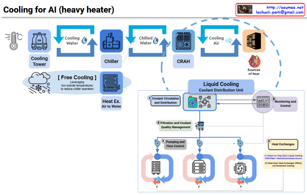
This diagram illustrates the evolution of data center cooling systems designed for high-heat AI workloads.

Traditional Cooling System (Top Section)

Three-Stage Cooling Process:

  1. Cooling Tower – Uses ambient air to cool water
  2. Chiller – Further refrigerates the cooled water
  3. CRAH (Computer Room Air Handler) – Distributes cold air to the server room

Free Cooling option is shown, which reduces chiller operation by leveraging low outside temperatures for energy savings.

New Approach for AI DC: Liquid Cooling System (Bottom Section)

To address extreme heat generation from high-density AI chips, a CDU (Coolant Distribution Unit) based liquid cooling system has been introduced.

Key Components:

โ‘  Coolant Circulation and Distribution

  • Direct coolant circulation system to servers

โ‘ก Heat Exchanges (Two Methods)

  • Direct-to-Chip (D2C) Liquid Cooling: Cold plate with manifold distribution system directly contacting chips
  • Rear-Door Heat Exchanger (RDHx): Heat exchanger mounted on rack rear door (immersion cooling)

โ‘ข Pumping and Flow Control

  • Pumps and flow control for coolant circulation

โ‘ฃ Filtration and Coolant Quality Management

  • Maintains coolant quality and removes contaminants

โ‘ค Monitoring and Control

  • Real-time monitoring and cooling performance control

Critical Differences

Traditional Method: Air cooling โ†’ Indirect, suitable for low-density workloads

AI DC Method: Liquid cooling โ†’ Direct, high-efficiency, capable of handling high TDP (Thermal Design Power) of AI chips

Liquid has approximately 25x better heat transfer efficiency than air, making it effective for cooling AI accelerators (GPUs, TPUs) that generate hundreds of watts to kilowatt-level heat.


Summary:

  1. Traditional data centers use air-based cooling (Cooling Tower โ†’ Chiller โ†’ CRAH), suitable for standard workloads.
  2. AI data centers require liquid cooling with CDU systems due to extreme heat from high-density AI chips.
  3. Liquid cooling offers direct-to-chip heat removal with 25x better thermal efficiency than air, supporting kW-level heat dissipation.

#AIDataCenter #LiquidCooling #DataCenterInfrastructure #CDU #ThermalManagement #DirectToChip #AIInfrastructure #GreenDataCenter #HeatDissipation #HyperscaleComputing #AIWorkload #DataCenterCooling #ImmersionCooling #EnergyEfficiency #NextGenDataCenter

With Claude

Power/Cooling impacts to AI Work

Power/Cooling Impacts on AI Work – Analysis

This slide summarizes research findings on how AI workloads impact power grids and cooling systems.

Key Findings:

๐Ÿ“Š Reliability & Failure Studies

  • Large-Scale ML Cluster Reliability (Meta, 2024/25)
    • 1024-GPU job MTTF (Mean Time To Failure): 7.9 hours
    • 8-GPU job: 47.7 days
    • 16,384-GPU job: 1.8 hours
    • โ†’ Larger jobs = higher failure risk due to cooling/power faults amplifying errors

๐Ÿ”Œ Silent Data Corruption (SDC)

  • SDC in LLM Training (2025)
    • Meta report: 6 SDC failures in 54-day pretraining run
    • Power droop, thermal stress โ†’ hardware faults โ†’ silent errors โ†’ training divergence

โšก Inference Energy Efficiency

  • LLM Inference Energy Consumption (2025)
    • GPT-4o query benchmarks:
      • Short: 0.43 Wh
      • Medium: ~3.71 Wh
    • Batch 4โ†’8: ~43% savings
    • Batch 8โ†’16: ~43% savings per prompt
    • โ†’ PUE & infrastructure efficiency significantly impact inference cost, delay, and carbon footprint

๐Ÿญ Grid-Level Instability

  • AI-Induced Power Grid Disruptions (2024)
    • Model training causes power transients
    • Dropouts โ†’ hardware resets
    • Grid-level instability โ†’ node-level errors (SDC, restarts) โ†’ LLM job failures

๐ŸŽฏ Summary:

  1. Large-scale AI workloads face exponentially higher failure rates – bigger jobs are increasingly vulnerable to power/cooling system issues, with 16K-GPU jobs failing every 1.8 hours.
  2. Silent data corruption from thermal/power stress causes undetected training failures, while inference efficiency can be dramatically improved through batch optimization (43% energy reduction).
  3. AI training creates a vicious cycle of grid instability – power transients trigger hardware faults that cascade into training failures, requiring robust infrastructure design for power stability and fault tolerance.

#AIInfrastructure #MLOps #DataCenterEfficiency #PowerManagement #AIReliability #LLMTraining #SilentDataCorruption #EnergyEfficiency #GridStability #AIatScale #HPC #CoolingSystem #AIFailures #SustainableAI #InferenceOptimization

With Claude

DC Cooling (R)

Data Center Cooling System Core Structure

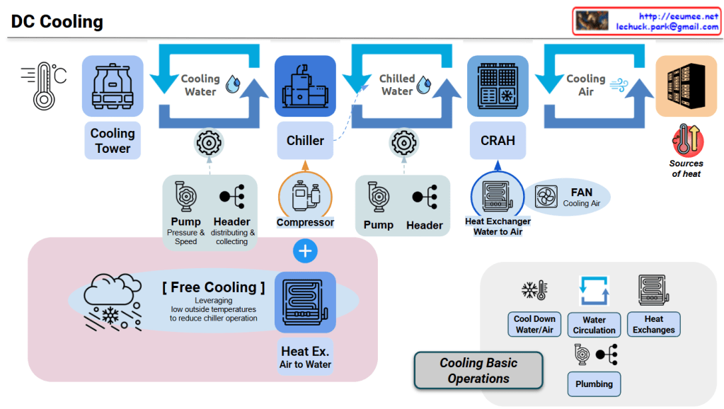
This diagram illustrates an integrated data center cooling system centered on chilled water/cooling water circulation and heat exchange.

Core Cooling Circulation Structure

Primary Loop: Cooling Water Loop

Cooling Tower โ†’ Cooling Water โ†’ Chiller โ†’ (Heat Exchange) โ†’ Cooling Tower

  • Cooling Tower: Dissipates heat from cooling water to atmosphere using outdoor air
  • Pump/Header: Controls cooling water pressure and flow rate through circulation pipes
  • Heat Exchange in Chiller: Cooling water exchanges heat with refrigerant to cool the refrigerant

Secondary Loop: Chilled Water Loop

Chiller โ†’ Chilled Water โ†’ CRAH โ†’ (Heat Exchange) โ†’ Chiller

  • Chiller: Generates chilled water (7-12ยฐC) through compressor and refrigerant cycle
  • Pump/Header: Circulates chilled water to CRAH units and returns it back
  • Heat Exchange in CRAH: Chilled water exchanges heat with air to cool the air

Tertiary Loop: Cooling Air Loop

CRAH โ†’ Cooling Air โ†’ Servers โ†’ Hot Air โ†’ CRAH

  • CRAH (Computer Room Air Handler): Generates cooling air through water-to-air heat exchanger
  • FAN: Forces circulation of cooling air throughout server room
  • Heat Absorption: Air absorbs server heat and returns to CRAH

Heat Exchange Critical Points

Heat Exchange #1: Inside Chiller

  • Cooling Water โ†” Refrigerant: Transfers refrigerant heat to cooling water in condenser
  • Refrigerant โ†” Chilled Water: Absorbs heat from chilled water to refrigerant in evaporator

Heat Exchange #2: CRAH

  • Chilled Water โ†” Air: Transfers air heat to chilled water in water-to-air heat exchanger
  • Chilled water temperature rises โ†’ Returns to chiller

Heat Exchange #3: Server Room

  • Hot Air โ†” Servers: Air absorbs heat from servers
  • Temperature-increased air โ†’ Returns to CRAH

Energy Efficiency: Free Cooling

Low-Temperature Outdoor Air โ†’ Air-to-Water Heat Exchanger โ†’ Chilled Water Cooling โ†’ Reduced Chiller Load

  • Condition: When outdoor temperature is sufficiently low
  • Effect: Reduces chiller operation and compressor power consumption (up to 30-50%)
  • Method: Utilizes natural cooling through cooling tower or dedicated heat exchanger

Cooling System Control Elements

Cooling Basic Operations Components:

  • Cool Down: Controls water/air temperature reduction
  • Water Circulation: Adjusts flow rate through pump speed/pressure control
  • Heat Exchanges: Optimizes heat exchanger efficiency
  • Plumbing: Manages circulation paths and pressure loss

Heat Flow Summary

Server Heat โ†’ Air โ†’ CRAH (Heat Exchange) โ†’ Chilled Water โ†’ Chiller (Heat Exchange) โ†’ 
Cooling Water โ†’ Cooling Tower โ†’ Atmospheric Discharge


Summary

This system efficiently removes server heat to the outdoor atmosphere through three cascading circulation loops (air โ†’ chilled water โ†’ cooling water) and three strategic heat exchange points (CRAH, Chiller, Cooling Tower). Free cooling optimization reduces energy consumption by up to 50% when outdoor conditions permit. The integrated pump/header network ensures precise flow control across all loops for maximum cooling efficiency.


#DataCenterCooling #ChilledWater #CRAH #FreeCooling #HeatExchange #CoolingTower #ThermalManagement #DataCenterInfrastructure #EnergyEfficiency #HVACSystem #CoolingLoop #WaterCirculation #ServerCooling #DataCenterDesign #GreenDataCenter

With Claude

MoE & More

MoE & More – Architecture Interpretation

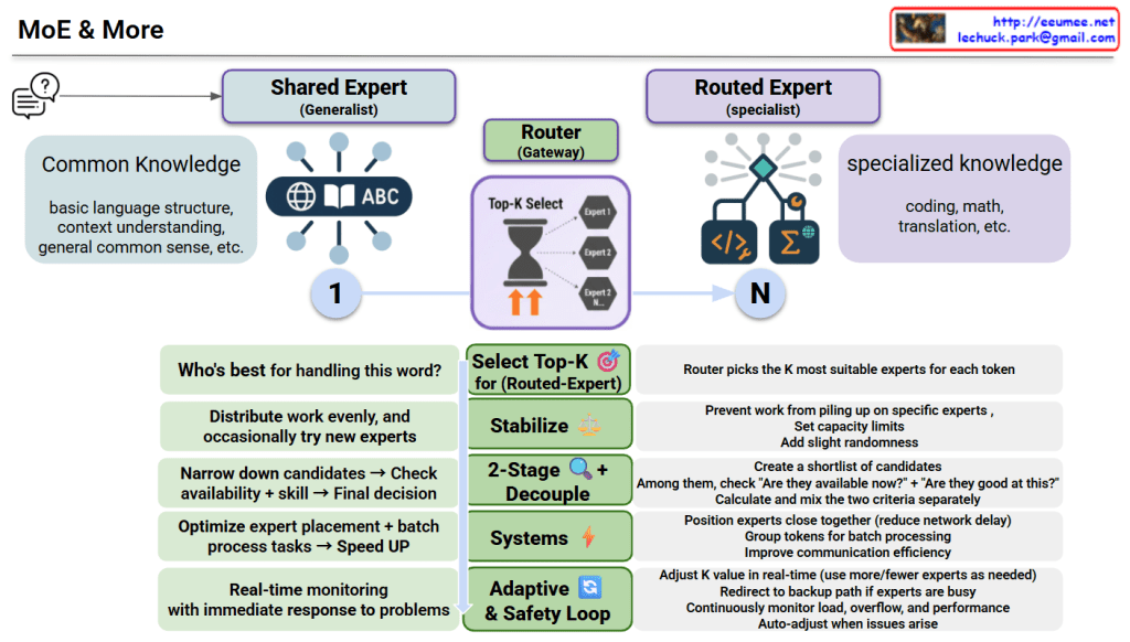
This diagram illustrates an advanced Mixture of Experts (MoE) model architecture.

Core Structure

1. Two Types of Experts

  • Shared Expert (Generalist)
    • Handles common knowledge: basic language structure, context understanding, general common sense
    • Applied universally to all tokens
  • Routed Expert (Specialist)
    • Handles specialized knowledge: coding, math, translation, etc.
    • Router selects the K most suitable experts for each token

2. Router (Gateway) Role

For each token, determines “Who’s best for handling this word?” by:

  • Selecting K experts out of N available specialists
  • Using Top-K selection mechanism

Key Optimization Techniques

Select Top-K ๐ŸŽฏ

  • Chooses K most suitable routed experts
  • Distributes work evenly and occasionally tries new experts

Stabilize โš–๏ธ

  • Prevents work from piling up on specific experts
  • Sets capacity limits and adds slight randomness

2-Stage Decouple ๐Ÿ”

  • Creates a shortlist of candidate experts
  • Separately checks “Are they available now?” + “Are they good at this?”
  • Calculates and mixes the two criteria separately before final decision
  • Validates availability and skill before selection

Systems โšก

  • Positions experts close together (reduces network delay)
  • Groups tokens for batch processing
  • Improves communication efficiency

Adaptive & Safety Loop ๐Ÿ”„

  • Adjusts K value in real-time (uses more/fewer experts as needed)
  • Redirects to backup path if experts are busy
  • Continuously monitors load, overflow, and performance
  • Auto-adjusts when issues arise

Purpose

This system enhances both efficiency and performance through:

  • Optimized expert placement
  • Accelerated batch processing
  • Real-time monitoring with immediate problem response

Summary

MoE & More combines generalist experts (common knowledge) with specialist experts (domain-specific skills), using an intelligent router to dynamically select the best K experts for each token. Advanced techniques like 2-stage decoupling, stabilization, and adaptive safety loops ensure optimal load balancing, prevent bottlenecks, and enable real-time adjustments for maximum efficiency. The result is a faster, more efficient, and more reliable AI system that scales intelligently.

#MixtureOfExperts #MoE #AIArchitecture #MachineLearning #DeepLearning #LLM #NeuralNetworks #AIOptimization #ScalableAI #RouterMechanism #ExpertSystems #AIEfficiency #LoadBalancing #AdaptiveAI #MLOps

With Claude

Power for AI

AI Data Center Power Infrastructure: 3 Key Transformations

Traditional Data Center Power Structure (Baseline)

Power Grid โ†’ Transformer โ†’ UPS โ†’ Server (220V AC)

  • Single power grid connection
  • Standard UPS backup (10-15 minutes)
  • AC power distribution
  • 200-300W per server

3 Critical Changes for AI Data Centers

๐Ÿ”ด 1. More Power (Massive Power Supply)

Key Changes:

  • Diversified power sources:
    • SMR (Small Modular Reactor) – Stable baseload power
    • Renewable energy integration
    • Natural gas turbines
    • Long-term backup generators + large fuel tanks

Why: AI chips (GPU/TPU) consume kW to tens of kW per server

  • Traditional server: 200-300W
  • AI server: 5-10 kW (25-50x increase)
  • Total data center power demand: Hundreds of MW scale

๐Ÿ”ด 2. Stable Power (Power Quality & Conditioning)

Key Changes:

  • 800V HVDC system – High-voltage DC transmission
  • ESS (Energy Storage System) – Large-scale battery storage
  • Peak Shaving – Peak load control and leveling
  • UPS + Battery/Flywheel – Instantaneous outage protection
  • Power conditioning equipment – Voltage/frequency stabilization

Why: AI workload characteristics

  • Instantaneous power surges (during inference/training startup)
  • High power density (30-100 kW per rack)
  • Power fluctuation sensitivity – Training interruption = days of work lost
  • 24/7 uptime requirements

๐Ÿ”ด 3. Server Power (High-Efficiency Direct DC Delivery)

Key Changes:

  • Direct-to-Chip DC power delivery
  • Rack-level battery systems (Lithium/Supercapacitor)
  • High-density power distribution

Why: Maximize efficiency

  • Eliminate ACโ†’DC conversion losses (5-15% efficiency gain)
  • Direct chip-level power supply – Minimize conversion stages
  • Ultra-high rack density support (100+ kW/rack)
  • Even minor voltage fluctuations are critical – Chip-level stabilization needed

Key Differences Summary

CategoryTraditional DCAI Data Center
Power ScaleFew MWHundreds of MW
Rack Density5-10 kW/rack30-100+ kW/rack
Power MethodAC-centricHVDC + Direct DC
Backup PowerUPS (10-15 min)Multi-tier (Generator+ESS+UPS)
Power StabilityStandardExtremely high reliability
Energy SourcesSingle gridMultiple sources (Nuclear+Renewable)

Summary

โœ… AI data centers require 25-50x more power per server, demanding massive power infrastructure with diversified sources including SMRs and renewables

โœ… Extreme workload stability needs drive multi-tier backup systems (ESS+UPS+Generator) and advanced power conditioning with 800V HVDC

โœ… Direct-to-chip DC power delivery eliminates conversion losses, achieving 5-15% efficiency gains critical for 100+ kW/rack densities

#AIDataCenter #DataCenterPower #HVDC #DirectDC #EnergyStorageSystem #PeakShaving #SMR #PowerInfrastructure #HighDensityComputing #GPUPower #DataCenterDesign #EnergyEfficiency #UPS #BackupPower #AIInfrastructure #HyperscaleDataCenter #PowerConditioning #DCPower #GreenDataCenter #FutureOfComputing

With Claude

Programming … AI

This image contrasts traditional programming, where developers must explicitly code rules and logic (shown with a flowchart and a thoughtful programmer), with AI, where neural networks automatically learn patterns from large amounts of data (depicted with a network diagram and a smiling programmer). It illustrates the paradigm shift from manually defining rules to machines learning patterns autonomously from data.

#AI #MachineLearning #Programming #ArtificialIntelligence #AIvsTraditionalProgramming