Cooling for AI (heavy heater)

AI Data Center Cooling System Architecture Analysis

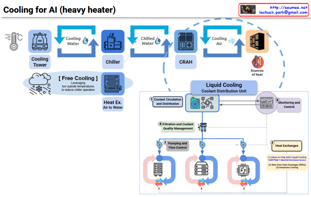
This diagram illustrates the evolution of data center cooling systems designed for high-heat AI workloads.

Traditional Cooling System (Top Section)

Three-Stage Cooling Process:

  1. Cooling Tower – Uses ambient air to cool water
  2. Chiller – Further refrigerates the cooled water
  3. CRAH (Computer Room Air Handler) – Distributes cold air to the server room

Free Cooling option is shown, which reduces chiller operation by leveraging low outside temperatures for energy savings.

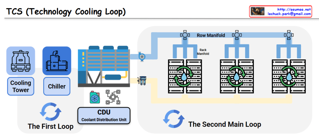
New Approach for AI DC: Liquid Cooling System (Bottom Section)

To address extreme heat generation from high-density AI chips, a CDU (Coolant Distribution Unit) based liquid cooling system has been introduced.
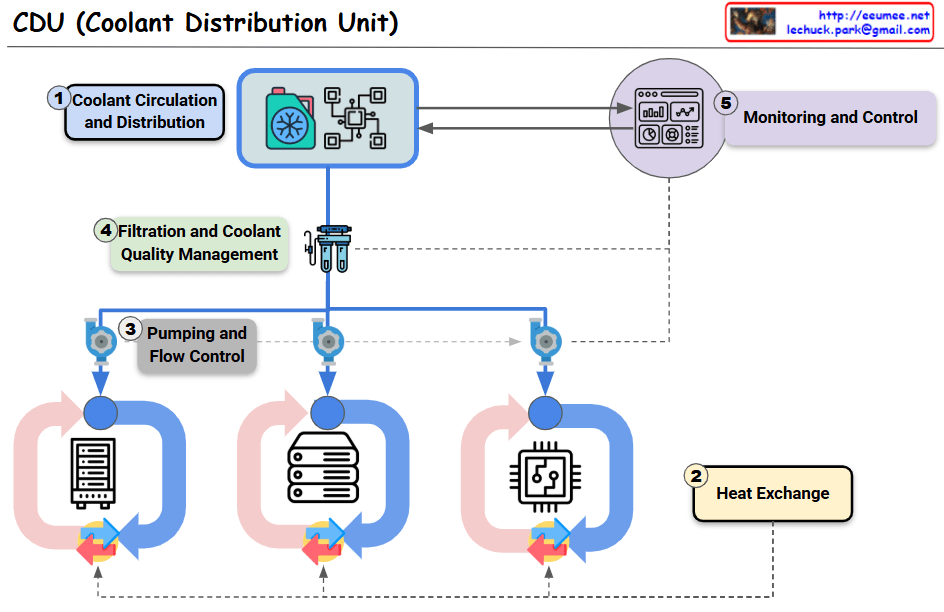
Key Components:

① Coolant Circulation and Distribution

  • Direct coolant circulation system to servers

② Heat Exchanges (Two Methods)

  • Direct-to-Chip (D2C) Liquid Cooling: Cold plate with manifold distribution system directly contacting chips
  • Rear-Door Heat Exchanger (RDHx): Heat exchanger mounted on rack rear door (immersion cooling)

③ Pumping and Flow Control

  • Pumps and flow control for coolant circulation

④ Filtration and Coolant Quality Management

  • Maintains coolant quality and removes contaminants

⑤ Monitoring and Control

  • Real-time monitoring and cooling performance control

Critical Differences

Traditional Method: Air cooling → Indirect, suitable for low-density workloads

AI DC Method: Liquid cooling → Direct, high-efficiency, capable of handling high TDP (Thermal Design Power) of AI chips

Liquid has approximately 25x better heat transfer efficiency than air, making it effective for cooling AI accelerators (GPUs, TPUs) that generate hundreds of watts to kilowatt-level heat.


Summary:

  1. Traditional data centers use air-based cooling (Cooling Tower → Chiller → CRAH), suitable for standard workloads.
  2. AI data centers require liquid cooling with CDU systems due to extreme heat from high-density AI chips.
  3. Liquid cooling offers direct-to-chip heat removal with 25x better thermal efficiency than air, supporting kW-level heat dissipation.

#AIDataCenter #LiquidCooling #DataCenterInfrastructure #CDU #ThermalManagement #DirectToChip #AIInfrastructure #GreenDataCenter #HeatDissipation #HyperscaleComputing #AIWorkload #DataCenterCooling #ImmersionCooling #EnergyEfficiency #NextGenDataCenter

With Claude

CDU Metrics & Control

This image shows a CDU (Coolant Distribution Unit) Metrics & Control System diagram illustrating the overall structure. The system can be organized as follows:

System Structure

Upper Section: CDU Structure

  • First Loop: CPU with Coolant Distribution Unit
  • Second Main Loop: Row Manifold and Rack Manifold configuration
  • Process Chill Water Supply/Return: Process chilled water circulation system

Lower Section: Data Collection & Control Devices

  • Control Devices:
    • Pump (Pump RPM, Rate of max speed)
    • Valve (Valve Open %)
  • Sensor Configuration:
    • Temperature & Pressure Sensors on manifolds
  • Supply System:
    • Rack Water Supply/Return

Main Control Methods

1. Fixed Pressure Control (Fixed Pressure Drop)

  • Primary Method: Maintaining fixed pressure drop between rack supply-return
  • Alternatives: Fixed flow rate, fixed supply temperature, fixed return temperature, fixed speed control

2. Approach Temperature Control

  • Primary Method: Maintaining constant approach temperature
  • Alternatives: Fixed open, fixed secondary supply temperature control

Summary

This CDU system provides precise cooling control for data centers through dual management of pressure and temperature. The system integrates sensor feedback from manifolds with pump and valve control to maintain optimal cooling conditions across server racks.

#CDU #CoolantDistribution #DataCenterCooling #TemperatureControl #PressureControl #ThermalManagement

with Claude

CDU ( OCP Project Deschutes ) Numbers

OCP CDU (Deschutes) Standard Overview

The provided visual summarizes the key performance metrics of the CDU (Cooling Distribution Unit) that adheres to the OCP (Open Compute Project) ‘Project Deschutes’ specification. This CDU is designed for high-performance computing environments, particularly for massive-scale liquid cooling of AI/ML workloads.


Key Performance Indicators

  • System Availability: The primary target for system availability is 99.999%. This represents an extremely high level of reliability, with less than 5 minutes and 15 seconds of downtime per year.
  • Thermal Load Capacity: The CDU is designed to handle a thermal load of up to 2,000 kW, which is among the highest thermal capacities in the industry.
  • Power Usage: The CDU itself consumes 74 kW of power.
  • IT Flow Rate: It supplies coolant to the servers at a rate of 500 GPM (approximately 1,900 LPM).
  • Operating Pressure: The overall system operating pressure is within a range of 0-130 psig (approximately 0-900 kPa).
  • IT Differential Pressure: The pressure difference required on the server side is 80-90 psi (approximately 550-620 kPa).
  • Approach Temperature: The approach temperature, a key indicator of heat exchange efficiency, is targeted at ≤3∘C. A lower value is better, as it signifies more efficient heat removal.

Why Cooling is Crucial for GPU Performance

Cooling has a direct and significant impact on GPU performance and stability. Because GPUs are highly sensitive to heat, if they are not maintained within an optimal temperature range, they will automatically reduce their performance through a process called thermal throttling to prevent damage.

The ‘Project Deschutes’ CDU is engineered to prevent this by handling a massive thermal load of 2,000 kW with a powerful 500 GPM flow rate and a low approach temperature of ≤3∘C. This robust cooling capability ensures that GPUs can operate at their maximum potential without being limited by heat, which is essential for maximizing performance in demanding AI workloads.

with Gemini

TCS (Technology Cooling Loop)

This image shows a diagram of the TCS (Technology Cooling Loop) system structure.

System Components

The First Loop:

  • Cooling Tower: Dissipates heat to the atmosphere
  • Chiller: Generates chilled water
  • CDU (Coolant Distribution Unit): Distributes coolant throughout the system

The Second Main Loop:

  • Row Manifold: Distributes cooling water to each server rack row
  • Rack Manifold: Individual rack-level cooling water distribution system
  • Server Racks: IT equipment racks that require cooling

System Operation

  1. Primary Loop: The cooling tower releases heat to the outside air, while the chiller produces chilled water that is supplied to the CDU
  2. Secondary Loop: Coolant distributed from the CDU flows through the Row Manifold to each server rack’s Rack Manifold, cooling the servers
  3. Circulation System: The heated coolant returns to the CDU where it is re-cooled through the primary loop

This is an efficient cooling system used in data centers and large-scale IT facilities. It systematically removes heat generated by server equipment to ensure stable operations through a two-loop architecture that separates the heat rejection process from the precision cooling delivery to IT equipment.

With Claude

CDU (Coolant Distribution Unit)

This image illustrates a Coolant Distribution Unit (CDU) with its key components and the liquid cooling system implemented in modern AI data centers. The diagram shows five primary components:

  1. Coolant Circulation and Distribution: The central component that efficiently distributes liquid coolant throughout the entire system.
  2. Heat Exchange: This section removes heat absorbed by the liquid coolant to maintain the cooling system’s efficiency.
  3. Pumping and Flow Control: Includes pumps and control devices that precisely manage the movement of coolant throughout the system.
  4. Filtration and Coolant Quality Management: A filtration system that purifies the liquid coolant and maintains optimal quality for cooling efficiency.
  5. Monitoring and Control: An interface that provides real-time monitoring and control of the entire liquid cooling system.

The three devices shown at the bottom of the diagram represent different levels of liquid cooling application in modern AI data centers:

  • Rack-level liquid cooling
  • Individual server-level liquid cooling
  • Direct processor (CPU/GPU) chip-level liquid cooling

This diagram demonstrates how advanced liquid cooling technology has evolved from traditional air cooling methods to effectively manage the high heat generated in AI-intensive modern data centers. It shows an integrated approach where the CDU facilitates coolant circulation to efficiently remove heat at rack, server, and chip levels.

With Claude