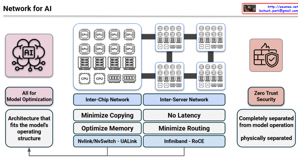
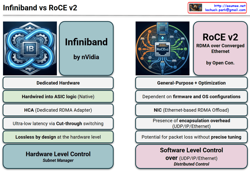
Large Scale Network Driven Design(2) Multi-Plane Fat-Tree & Low Latency

Comprehensive Interpretation: Large Scale Network Driven Design

This document outlines the technical blueprint for “Network Co-Design,” explaining how network architecture must evolve to support massive AI workloads (specifically LLMs) by balancing Bandwidth and Latency.

Here is the breakdown from an architect’s perspective:

1. Structural Efficiency: MPFT & MRFT (The “Green” Section)

This section answers the question: “How do we efficiently cluster thousands of GPUs?”

  • Massive Scalability: It proposes a Multi-Plane Fat-Tree (MPFT) structure using 400G InfiniBand (IB) switches, theoretically capable of scaling up to 16,384 GPUs. This mirrors the scale of NVIDIA SuperPods.
  • Multi-Rail Architecture (MRFT): MRFT utilizes two distinct network planes. Think of this as adding a second level to a highway to double the lanes. It achieves higher bandwidth efficiency compared to traditional 2-tier Fat-Tree designs.
  • Software Optimization (NCCL): The hardware (MRFT) is fully utilized by NCCL (NVIDIA Collective Communications Library). NCCL acts as the traffic controller, ensuring the expanded physical bandwidth is saturated efficiently.
  • Latency Reduction (Packet Striping): The QP & Priority section highlights a critical mechanism where a single Queue Pair (QP) stripes packets across multiple ports simultaneously. This parallel transmission significantly reduces latency.
  • Current Bottlenecks: The design acknowledges limitations, such as InfiniBand’s lack of native support for out-of-order packet placement and the time overhead incurred during inter-plane communication (requires internal forwarding).

2. The Core of Performance: Low Latency & MoE (The “Blue” Section)

This section answers the question: “Why is low latency (and InfiniBand) non-negotiable?”

  • Sensitivity of MoE Models: Modern Mixture of Experts (MoE) models rely heavily on “Expert Parallelism,” which triggers frequent All-to-all communication. If the network lags even by hundreds of microseconds, the entire system performance degrades fataly.
  • RoCE vs. InfiniBand: The document draws a clear line. While RoCE (RDMA over Converged Ethernet) is cost-effective, InfiniBand (IB) is the superior choice for low-latency environments essential for AI training/inference.
  • Surprising Latency Metrics: It highlights a specific scenario: for small data transfers (e.g., 64 Bytes), InfiniBand can be faster than intra-node NVLink (specifically during Cross Leaf communication), proving its dominance in minimizing end-to-end latency.

Summary

  1. Scalable Architecture: The Multi-Plane (MPFT) and Multi-Rail (MRFT) Fat-Tree designs, optimized with NCCL, maximize bandwidth efficiency to support massive clusters of up to 16k GPUs.
  2. Latency Criticality: Modern AI workloads like Mixture of Experts (MoE) are hypersensitive to delay, making InfiniBand the preferred choice over RoCE due to its superior handling of All-to-all communication.
  3. Co-Design Strategy: Achieving peak AI performance requires a “Network Co-Design” approach where high-speed hardware (400G IB) and software protocols (Packet Striping) are tightly integrated to minimize end-to-end latency.

#AINetworking #DataCenterArchitecture #InfiniBand #NCCL #LowLatency #HPC #GPUScaling #MoE #NetworkDesign #AIInfrastructure #DeepseekV3

WIth Gemini

Interconnection Driven Design (Deepseek v3)

Interconnection Driven Design

This image outlines a technical approach to solving bottlenecks in High-Performance Computing (HPC) and AI/LLM infrastructure. It is categorized into three main rows, each progressing from a Problem to a Solution, and finally to a hardware-level Final Optimization.

1. Convergence of Scale-Up and Scale-Out

Focuses on resolving inefficiencies between server communication and GPU computation.

  • Problem (IB Communication): The speed of inter-server connections (e.g., InfiniBand) creates a bottleneck for total system performance.
  • Inefficiency (Streaming Multiprocessor): The GPU’s core computational units (SMs) waste resources handling network overhead instead of focusing on actual calculations.
  • Solution (SM Offload): Communication tasks are delegated (offloaded) to dedicated coprocessors, allowing SMs to focus exclusively on computation.
  • Final Optimization (Unified Network Adapter): Physically integrating intra-node and inter-node communication into a single Network Interface Card (NIC) to minimize data movement paths.

2. Bandwidth Contention & Latency

Addresses the limitations of data bandwidth and processing delays.

  • Problem (KV Cache): Reusable token data for LLM inference frequently travels between the CPU and GPU, consuming significant bandwidth.
  • Bottleneck (PCIe): The primary interconnect has limited bandwidth, leading to contention and performance degradation during traffic spikes.
  • Solution (Traffic Class – TC): A prioritization mechanism (QoS) ensures urgent, latency-sensitive traffic is processed before less critical data.
  • Final Optimization (I/O Die Chiplet Integration): Integrating network I/O directly alongside the GPU die bypasses PCIe entirely, eliminating contention and drastically reducing latency.

3. Node-Limited Routing

Optimizes data routing strategies for distributed neural networks.

  • Key Tech (NVLink): A high-speed, intra-node GPU interconnect strategically used to maximize local data transfer.
  • Context (Experts): Neural network modules (MoE – Mixture of Experts) are distributed across various nodes, requiring activation for specific tokens.
  • Solution/Strategy (Minimize IB Cost): Reducing overhead by restricting slow inter-node usage (InfiniBand) to a single hop while distributing data internally via fast NVLink.
  • Final Optimization (Node-Limited): Algorithms restrict the selection of “Experts” (modules) to a limited node group, reducing inter-node traffic and guaranteeing communication efficiency.

Summary

  1. Integration: The design overcomes system bottlenecks by physically unifying network adapters and integrating I/O dies directly with GPUs to bypass slow connections like PCIe.
  2. Offloading & Prioritization: It improves efficiency by offloading network tasks from GPU cores (SMs) and prioritizing urgent traffic (Traffic Class) to reduce latency.
  3. Routing Optimization: It utilizes “Node-Limited” routing strategies to maximize high-speed local connections (NVLink) and minimize slower inter-server communication in distributed AI models.

#InterconnectionDrivenDesign #AIInfrastructure #GPUOptimization #HPC #ChipletIntegration #NVLink #LatencyReduction #LLMHardware #infiniband

With Gemini

Multi-Plane Network Topology ( deepseek v3)

Multi-Plane Network Topology for Scalable AI Clusters

Core Architecture (Left – Green Sections)

Topology Structure

  • Adopts 2-Tier Fat-Tree (FT2) architecture for reduced latency and cost efficiency compared to 3-Tier
  • Achieves massive scale connections at much lower cost than 3-tier architectures

Multi-Plane Design

  • 8-Plane Architecture: Each node contains 8 GPUs and 8 IB NICs
  • 1:1 Mapping: Dedicates specific GPU-NIC pairs to separate planes

NIC Specifications

  • Hardware: 400G InfiniBand (ConnectX-7)
  • Resilience: Multi-port connectivity ensures robustness against single-port failures

Maximum Scalability

  • Theoretically supports up to 16,384 GPUs within the 2-tier structure

Advantages (Center – Purple Sections)

Cost Efficiency: Connects massive scale at much lower cost compared to 3-tier architectures

Ultra-Low Latency: Fewer network hops ensure rapid data transfer, ideal for latency-sensitive AI models like MoE

Traffic Isolation: Independent communication lanes (planes) prevent congestion or faults in one lane from affecting others

Proven Performance: Validated in large-scale tests with 2048 GPUs, delivering stable and high-speed communication

Challenges (Right – Orange Sections)

Packet Ordering Issues: Current hardware (ConnectX-7) has limitations in handling out-of-order data packets

Cross-Plane Delays: Moving data between different network planes requires extra internal forwarding, causing higher latency during AI inference

Smarter Routing Needed: Standard traffic methods (ECMP) are inefficient for AI; requires Adaptive Routing that intelligently selects the best path based on network traffic

Hardware Integration: Future hardware should build network components directly into main chips to remove bottlenecks and speed up communication


Summary

This document presents a multi-plane network topology using 2-tier Fat-Tree architecture that scales AI clusters up to 16,384 GPUs cost-effectively with ultra-low latency. The 8-plane design with 1:1 GPU-NIC mapping provides traffic isolation and resilience, though challenges remain in packet ordering and cross-plane communication. Future improvements require smarter routing algorithms and deeper hardware-network integration to optimize AI workload performance.

#AIInfrastructure #DataCenterNetworking #HPC #InfiniBand #GPUCluster #NetworkTopology #FatTree #ScalableComputing #MLOps #AIHardware #DistributedComputing #CloudInfrastructure #NetworkArchitecture #DeepLearning #AIatScale

Large Scale Network Driven Design ( Deepseek V3)

Deepseek v3 Large-Scale Network Architecture Analysis

This image explains the Multi-Plane Fat-Tree network structure of Deepseek v3.

Core Architecture

1. 8-Plane Architecture

  • Consists of eight independent network channels (highways)
  • Maximizes network bandwidth and distributes traffic for enhanced scalability

2. Fat-Tree Topology

  • Two-layer switch structure:
    • Leaf SW (Leaf Switches): Directly connected to GPUs
    • Spine SW (Spine Switches): Interconnect leaf switches
  • Enables high-speed communication among all nodes (GPUs) while minimizing switch contention

3. GPU/IB NIC Pair

  • Each GPU is paired with a dedicated Network Interface Card (NIC)
  • Each pair is exclusively assigned to one of the eight planes to initiate communication

Communication Methods

NVLink

  • Ultra-high-speed connection between GPUs within the same node
  • Fast data transfer path used for intra-node communication

Cross-plane Traffic

  • Occurs when communication happens between different planes
  • Requires intra-node forwarding through another NIC, PCIe, or NVLink
  • Primary factor that increases latency

Network Optimization Process

The workflow below minimizes latency and prevents network congestion:

  1. Workload Analysis
  2. All to All (analyzing all-to-all communication patterns)
  3. Plane & Layer Set (plane and layer assignment)
  4. Profiling (Hot-path opt K) (hot-path optimization)
  5. Static Routing (Hybrid) (hybrid static routing approach)

Goal: Low latency & no jamming

Scalability

This design is a scale-out network for large-scale distributed training supporting 16,384+ GPUs. Each plane operates independently to maximize overall system throughput.


3-Line Summary

Deepseek v3 uses an 8-plane fat-tree network architecture that connects 16,384+ GPUs through independent communication channels, minimizing contention and maximizing bandwidth. The two-layer switch topology (Spine and Leaf) combined with dedicated GPU-NIC pairs enables efficient traffic distribution across planes. Cross-plane traffic management and hot-path optimization ensure low-latency, high-throughput communication for large-scale AI training.

#DeepseekV3 #FatTreeNetwork #MultiPlane #NetworkArchitecture #ScaleOut #DistributedTraining #AIInfrastructure #GPUCluster #HighPerformanceComputing #NVLink #DataCenterNetworking #LargeScaleAI

With Claude

NVLink, Infiniband

This diagram compares two GPU networking technologies: NVLink and InfiniBand, both essential for parallel computing expansion.

On the left side, the “NVLink” section shows multiple GPUs connected vertically through purple interconnect bars. This represents the “Scale UP” approach, where GPUs are vertically scaled within a single system for tight integration.

On the right side, the “InfiniBand” section demonstrates how multiple server nodes connect through an InfiniBand network. This illustrates the “Scale Out” approach, where computing power expands horizontally across multiple independent systems.

Both technologies share the common goal of expanding parallel processing capabilities, but they do so in different architectural approaches. NVLink focuses on high-speed, direct connections between GPUs in a single system, while InfiniBand specializes in networking across multiple systems to support distributed computing environments.

The optimization of these expansion configurations is crucial for maximizing performance in high-performance computing, AI training, and other compute-intensive applications. System architects must carefully consider workload characteristics, data movement patterns, and scaling requirements when choosing between these technologies or determining how to best implement them together in hybrid configurations.

With Claude

Network for GPUs

with a Claude’s Help
The network architecture demonstrates 3 levels of connectivity technologies:

  1. NVLink (Single node Parallel processing)
  • Technology for directly connecting GPUs within a single node
  • Supports up to 256 GPU connections
  • Physical HBM (High Bandwidth Memory) sharing
  • Optimized for high-performance GPU parallel processing within individual servers
  1. NVSwitch
  • Switching technology that extends NVLink limitations
  • Provides logical HBM sharing
  • Key component for large-scale AI model operations
  • Enables complete mesh network configuration between GPU groups
  • Efficiently connects multiple GPU groups within One Box Server
  • Targets large AI model workloads
  1. InfiniBand
  • Network technology for server clustering
  • Supports RDMA (Remote Direct Memory Access)
  • Used for distributed computing and HPC (High Performance Computing) tasks
  • Implements hierarchical network topology
  • Enables large-scale cluster configuration across multiple servers
  • Focuses on distributed and HPC workloads

This 3-tier architecture provides scalability through:

  • GPU parallel processing within a single server (NVLink)
  • High-performance connectivity between GPU groups within a server (NVSwitch)
  • Cluster configuration between multiple servers (InfiniBand)

The architecture enables efficient handling of various workload scales, from small GPU tasks to large-scale distributed computing. It’s particularly effective for maximizing GPU resource utilization in large-scale AI model training and HPC workloads.

Key Benefits:

  • Hierarchical scaling from single node to multi-server clusters
  • Efficient memory sharing through both physical and logical HBM
  • Flexible topology options for different computing needs
  • Optimized for both AI and high-performance computing workloads
  • Comprehensive solution for GPU-based distributed computing

This structure provides a complete solution from single-server GPU operations to complex distributed computing environments, making it suitable for a wide range of high-performance computing needs.

Infiniband

From claude with some prompting
The image correctly depicts the essential hardware elements of an InfiniBand network, including the PCI interface, Host Channel Adapters (HCAs), InfiniBand Switch, and InfiniBand cables connecting the HCAs to the switch.

It highlights RDMA (Remote Direct Memory Access) as a key technology that enables read/write operations without CPU involvement, facilitated by APIs for controlling the HCAs.

The hardware components listed (HCA, InfiniBand Switch, InfiniBand Cable) are accurate.

However, there is one potential inaccuracy in the details provided. The stated latency of 1.5μs seems quite low for an end-to-end InfiniBand communication. Typical InfiniBand latencies are in the range of a few microseconds, depending on the specific InfiniBand generation and configuration.

Additionally, while the image mentions a “400Gbps High Data Rate,” it’s important to note that this is an aggregate bandwidth across multiple links or ports, not necessarily the speed of a single link.

Overall, the image effectively conveys the main concepts and components of InfiniBand technology, with just a minor potential discrepancy in the stated latency value.