The High Stakes of Ultra-High Density: Seconds to React, Massive Costs

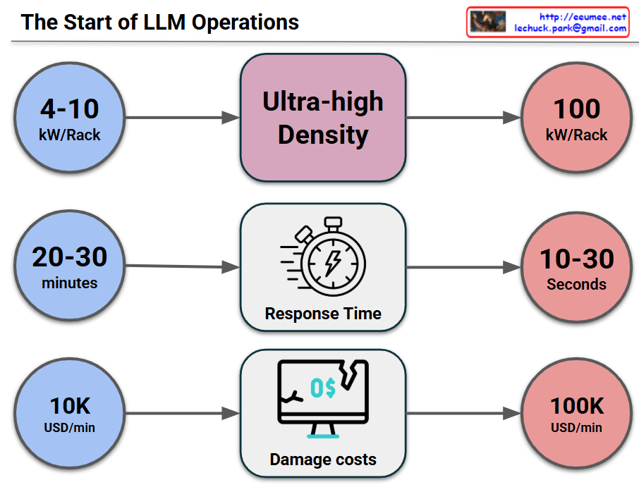
This image visually compares the critical changes and risks that occur when a data center or IT infrastructure transitions to an “Ultra-high Density” environment across three key metrics.

1. Surge in Power Density (Top Row)

  • Past/Standard Environment (Blue): Racks typically operated at a power density of 4-10 kW per Rack.
  • Transition (Middle): The shift toward Ultra-high Density infrastructure (driven by AI, High-Performance Computing, etc.).
  • Current/Ultra-high Density (Red): Power density explodes to 100 kW per Rack, which is a 10-fold increase.

2. Drastic Drop in Response Time (Middle Row)

  • Past/Standard Environment: In the event of a cooling failure or system issue, operators had a comfortable golden window of 20-30 minutes to react before systems went down.
  • Transition: Focusing on the change in Response Time.
  • Current/Ultra-high Density: Due to the massive, instantaneous heat generation, the reaction window plummets to a mere 10-30 seconds. This makes manual human intervention practically impossible.

3. Explosion of Damage Costs (Bottom Row)

  • Past/Standard Environment: The financial loss caused by system downtime was around $10,000 (10K USD) per minute.
  • Transition: Focusing on the change in Damage costs.
  • Current/Ultra-high Density: Because of the high value of the equipment and the critical nature of the data being processed, the cost of downtime skyrockets to $100,000 (100K USD) per minuteโ€”a 10x increase.

๐Ÿ’ก Overall Summary

The core message of this infographic is a strong warning: “In ultra-high density environments reaching 100kW per rack, the window for disaster response shrinks from minutes to mere seconds, while the financial loss per minute multiplies tenfold.” This perfectly illustrates why immediate, automated cooling and response systems (such as liquid cooling or AI-driven automation) are no longer optional, but mandatory for modern data centers.


#DataCenter #UltraHighDensity #HighDensityComputing #ITInfrastructure #Downtime #CostOfDowntime #RiskManagement

With Gemini

Air Cooling For 30kw/Rack

Why Air Cooling Fails at 30kW+

  • Noise & Vibration: Achieving 6,000 CMH airflow generates 90-100dB noise and vibrations that damage hardware.
  • Space Loss: Massive cooling fans displace GPUs/CPUs, drastically reducing compute density.
  • Power Waste: Fan power consumption grows cubically (V^3), causing a significant spike in PUE (Power Usage Effectiveness).

Conclusion: At 30kW/Rack, air cooling hits a physical and economic “wall”. Transitioning to Liquid Cooling is mandatory for next-generation AI Data Centers.


#AIDataCenter #LiquidCooling #ThermalManagement #30kWRack #DataCenterEfficiency #PUE #HighDensityComputing #GPUCooling

Power for AI

AI Data Center Power Infrastructure: 3 Key Transformations

Traditional Data Center Power Structure (Baseline)

Power Grid โ†’ Transformer โ†’ UPS โ†’ Server (220V AC)

  • Single power grid connection
  • Standard UPS backup (10-15 minutes)
  • AC power distribution
  • 200-300W per server

3 Critical Changes for AI Data Centers

๐Ÿ”ด 1. More Power (Massive Power Supply)

Key Changes:

  • Diversified power sources:
    • SMR (Small Modular Reactor) – Stable baseload power
    • Renewable energy integration
    • Natural gas turbines
    • Long-term backup generators + large fuel tanks

Why: AI chips (GPU/TPU) consume kW to tens of kW per server

  • Traditional server: 200-300W
  • AI server: 5-10 kW (25-50x increase)
  • Total data center power demand: Hundreds of MW scale

๐Ÿ”ด 2. Stable Power (Power Quality & Conditioning)

Key Changes:

  • 800V HVDC system – High-voltage DC transmission
  • ESS (Energy Storage System) – Large-scale battery storage
  • Peak Shaving – Peak load control and leveling
  • UPS + Battery/Flywheel – Instantaneous outage protection
  • Power conditioning equipment – Voltage/frequency stabilization

Why: AI workload characteristics

  • Instantaneous power surges (during inference/training startup)
  • High power density (30-100 kW per rack)
  • Power fluctuation sensitivity – Training interruption = days of work lost
  • 24/7 uptime requirements

๐Ÿ”ด 3. Server Power (High-Efficiency Direct DC Delivery)

Key Changes:

  • Direct-to-Chip DC power delivery
  • Rack-level battery systems (Lithium/Supercapacitor)
  • High-density power distribution

Why: Maximize efficiency

  • Eliminate ACโ†’DC conversion losses (5-15% efficiency gain)
  • Direct chip-level power supply – Minimize conversion stages
  • Ultra-high rack density support (100+ kW/rack)
  • Even minor voltage fluctuations are critical – Chip-level stabilization needed

Key Differences Summary

CategoryTraditional DCAI Data Center
Power ScaleFew MWHundreds of MW
Rack Density5-10 kW/rack30-100+ kW/rack
Power MethodAC-centricHVDC + Direct DC
Backup PowerUPS (10-15 min)Multi-tier (Generator+ESS+UPS)
Power StabilityStandardExtremely high reliability
Energy SourcesSingle gridMultiple sources (Nuclear+Renewable)

Summary

โœ… AI data centers require 25-50x more power per server, demanding massive power infrastructure with diversified sources including SMRs and renewables

โœ… Extreme workload stability needs drive multi-tier backup systems (ESS+UPS+Generator) and advanced power conditioning with 800V HVDC

โœ… Direct-to-chip DC power delivery eliminates conversion losses, achieving 5-15% efficiency gains critical for 100+ kW/rack densities

#AIDataCenter #DataCenterPower #HVDC #DirectDC #EnergyStorageSystem #PeakShaving #SMR #PowerInfrastructure #HighDensityComputing #GPUPower #DataCenterDesign #EnergyEfficiency #UPS #BackupPower #AIInfrastructure #HyperscaleDataCenter #PowerConditioning #DCPower #GreenDataCenter #FutureOfComputing

With Claude