This diagram illustrates the GPU’s power and thermal management system.
Key Components
1. Two Throttling Triggers
Power Throttling: Throttling triggered by power limits
Thermal Throttling: Throttling triggered by temperature limits
2. Different Control Approaches
Power Limit (Budget) Controller: Slow, Linear Step Down
Thermal Safety Controller: Fast, Hard Step Down
This aggressive response is necessary because overheating can cause immediate hardware damage
3. Priority Gate
Receives signals from both controllers and determines which limitation to apply.
4. PMU/SMU/DVFS Controller
The Common Control Unit that manages:
PMU: Power Management Unit
SMU: System Management Unit
DVFS: Dynamic Voltage and Frequency Scaling
5. Actual Adjustment Mechanisms
Clock Domain Controller: Reduces GPU Frequency
Voltage Regulator: Reduces GPU Voltage
6. Final Result
Lower Power/Temp (Throttled): Reduced power consumption and temperature in throttled state
Core Principle
When the GPU reaches power budget or temperature limits, it automatically reduces performance to protect the system. By lowering both frequency and voltage simultaneously, it effectively reduces power consumption (P ∝ V²f).
Summary
GPU throttling uses two controllers—power (slow, linear) and thermal (fast, aggressive)—that feed into a shared PMU/SMU/DVFS system to dynamically reduce clock frequency and voltage. Thermal throttling responds more aggressively than power throttling because overheating poses immediate hardware damage risks. The end result is lower power consumption and temperature, sacrificing performance to maintain system safety and longevity.
3 Layers for Digital Operations – Comprehensive Analysis
This diagram presents an advanced three-layer architecture for digital operations, emphasizing continuous feedback loops and real-time decision-making.
🔄 Overall Architecture Flow
The system operates through three interconnected environments that continuously update each other, creating an intelligent operational ecosystem.
1️⃣ Micro Layer: Real-time Digital Twin Environment (Purple)
Purpose
Creates a virtual replica of physical assets for real-time monitoring and simulation.
Key Components
Digital Twin Technology: Mirrors physical operations in real-time
Real-time Real-Model: Processes high-resolution data streams instantaneously
Continuous Synchronization: Updates every change from physical assets
Data Flow
Data Sources (Servers, Networks, Manufacturing Equipment, IoT Sensors) → High Resolution Data Quality → Real-time Real-Model → Digital Twin
Function
Provides granular, real-time visibility into operations
Enables predictive maintenance and anomaly detection
Simulates scenarios before physical implementation
Serves as the foundation for higher-level decision-making
2️⃣ Macro Layer: LLM-based AI Agent Environment (Pink)
Purpose
Analyzes real-time data, identifies events, and makes intelligent autonomous decisions using AI.
Analyzes patterns and trends from Digital Twin data
Generates actionable insights and recommendations
Automates routine decision-making processes
Provides context-aware responses using RAG technology
Escalates complex issues to human operators
3️⃣ Human Layer: Operator Decision Environment (Green)
Purpose
Enables human oversight, strategic decision-making, and intervention when needed.
Key Components
Human-in-the-loop: Keeps humans in control of critical decisions
Well-Cognitive Interface: Presents data for informed judgment
Analytics Dashboard: Visualizes trends and insights
Data Flow
Both Digital Twin (Micro) and AI Agent (Macro) feed into → Human Layer for Well-Cognitive Decision Making
Function
Reviews AI recommendations and Digital Twin status
Makes strategic and high-stakes decisions
Handles exceptions and edge cases
Validates AI agent actions
Provides domain expertise and contextual understanding
Ensures ethical and business-aligned outcomes
🔁 Continuous Update Loop: The Key Differentiator
Feedback Mechanism
All three layers are connected through Continuous Update pathways (red arrows), creating a closed-loop system:
Human Layer → feeds decisions back to Data Sources
Micro Layer → continuously updates Human Layer
Macro Layer → continuously updates Human Layer
System-wide → all layers update the central processing and data sources
Benefits
Adaptive Learning: System improves based on human decisions
Real-time Optimization: Immediate response to changes
Knowledge Accumulation: RAG database grows with operations
Closed-loop Control: Decisions are implemented and their effects monitored
🎯 Integration Points
From Physical to Digital (Left → Right)
High-resolution data from multiple sources
Well-defined deterministic processing ensures data quality
Parallel paths: Real-time model (Micro) and Event logging (Macro)
From Digital to Action (Right → Left)
Human decisions informed by both layers
Actions feed back to physical systems
Results captured and analyzed in next cycle
💡 Key Innovation: Three-Way Synergy
Micro (Digital Twin): “What is happening right now?”
Macro (AI Agent): “What does it mean and what should we do?”
Human: “Is this the right decision given our goals?”
Each layer compensates for the others’ limitations:
Digital Twins provide accuracy but lack context
AI Agents provide intelligence but need validation
Humans provide wisdom but need information support
📝 Summary
This architecture integrates three operational environments: the Micro Layer uses real-time data to maintain Digital Twins of physical assets, the Macro Layer employs LLM-based AI Agents with RAG to analyze events and generate intelligent recommendations, and the Human Layer ensures well-cognitive decision-making through human-in-the-loop oversight. All three layers continuously update each other and feed decisions back to the operational systems, creating a self-improving closed-loop architecture. This synergy combines real-time precision, artificial intelligence, and human expertise to achieve optimal digital operations.
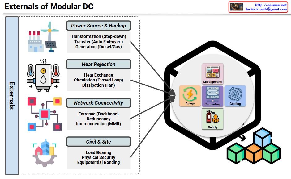
This diagram illustrates the external infrastructure systems that support a Modular Data Center (Modular DC).
Main Components
1. Power Source & Backup
Transformation (Step-down transformer)
Transfer switch (Auto Fail-over)
Generation (Diesel/Gas generators)
Ensures stable power supply and emergency backup capabilities.
2. Heat Rejection
Heat Exchange equipment
Circulation system (Closed Loop)
Dissipation system (Fan-based)
Cooling infrastructure that removes heat generated from the data center to the outside environment.
3. Network Connectivity
Entrance (Backbone connection)
Redundancy configuration
Interconnection (MMR – Meet Me Room)
Provides connectivity and telecommunication infrastructure with external networks.
4. Civil & Site
Load Bearing structures
Physical Security facilities
Equipotential Bonding
Handles building foundation and physical security requirements.
Internal Management Systems
The module integrates the following management elements:
Management: Integrated control system
Power: Power management
Computing: Computing resource management
Cooling: Cooling system control
Safety: Safety management
Summary
Modular data centers require four critical external infrastructure systems: power supply with backup generation, heat rejection for thermal management, network connectivity for communications, and civil/site infrastructure for physical foundation and security. These external systems work together to support the internal management components (power, computing, cooling, and safety) within the modular unit. This architecture enables rapid deployment while maintaining enterprise-grade reliability and scalability.
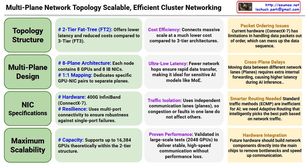
Multi-Plane Network Topology for Scalable AI Clusters
Core Architecture (Left – Green Sections)
Topology Structure
Adopts 2-Tier Fat-Tree (FT2) architecture for reduced latency and cost efficiency compared to 3-Tier
Achieves massive scale connections at much lower cost than 3-tier architectures
Multi-Plane Design
8-Plane Architecture: Each node contains 8 GPUs and 8 IB NICs
1:1 Mapping: Dedicates specific GPU-NIC pairs to separate planes
NIC Specifications
Hardware: 400G InfiniBand (ConnectX-7)
Resilience: Multi-port connectivity ensures robustness against single-port failures
Maximum Scalability
Theoretically supports up to 16,384 GPUs within the 2-tier structure
Advantages (Center – Purple Sections)
Cost Efficiency: Connects massive scale at much lower cost compared to 3-tier architectures
Ultra-Low Latency: Fewer network hops ensure rapid data transfer, ideal for latency-sensitive AI models like MoE
Traffic Isolation: Independent communication lanes (planes) prevent congestion or faults in one lane from affecting others
Proven Performance: Validated in large-scale tests with 2048 GPUs, delivering stable and high-speed communication
Challenges (Right – Orange Sections)
Packet Ordering Issues: Current hardware (ConnectX-7) has limitations in handling out-of-order data packets
Cross-Plane Delays: Moving data between different network planes requires extra internal forwarding, causing higher latency during AI inference
Smarter Routing Needed: Standard traffic methods (ECMP) are inefficient for AI; requires Adaptive Routing that intelligently selects the best path based on network traffic
Hardware Integration: Future hardware should build network components directly into main chips to remove bottlenecks and speed up communication
Summary
This document presents a multi-plane network topology using 2-tier Fat-Tree architecture that scales AI clusters up to 16,384 GPUs cost-effectively with ultra-low latency. The 8-plane design with 1:1 GPU-NIC mapping provides traffic isolation and resilience, though challenges remain in packet ordering and cross-plane communication. Future improvements require smarter routing algorithms and deeper hardware-network integration to optimize AI workload performance.
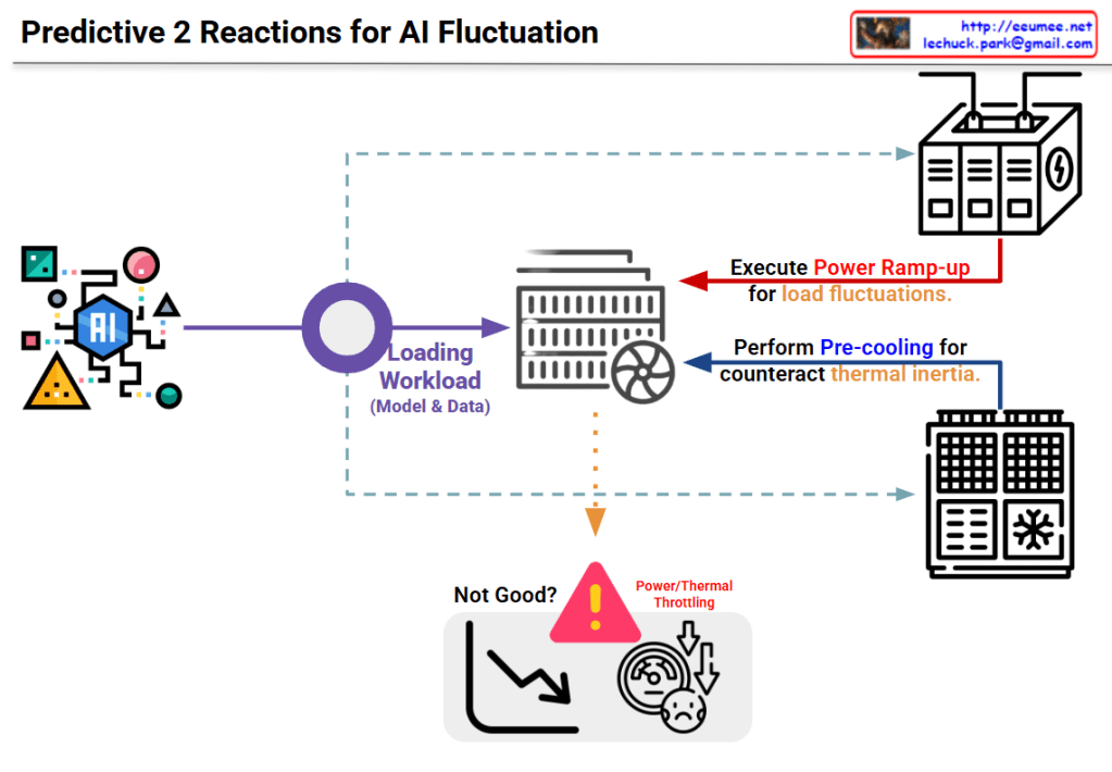
Image Interpretation: Predictive 2-Stage Reactions for AI Fluctuation
This diagram illustrates a two-stage predictive strategy to address load fluctuation issues in AI systems.
System Architecture
Input Stage:
The AI model on the left generates various workloads (model and data)
Processing Stage:
Generated workloads are transferred to the central server/computing system
Two-Stage Predictive Reaction Mechanism
Stage 1: Power Ramp-up
Purpose: Prepare for load fluctuations
Method: The power supply system at the top proactively increases power in advance
Preventive measure to secure power before the load increases
Stage 2: Pre-cooling
Purpose: Counteract thermal inertia
Method: The cooling system at the bottom performs cooling in advance
Proactive response to lower system temperature before heat generation
Problem Scenario
The warning area at the bottom center shows problems that occur without these responses:
Power/Thermal Throttling
Performance degradation (downward curve in the graph)
System dissatisfaction state
Key Concept
This system proposes an intelligent infrastructure management approach that predicts rapid fluctuations in AI workloads and proactively adjusts power and cooling before actual loads occur, thereby preventing performance degradation.
Summary
This diagram presents a predictive two-stage reaction system for AI workload management that combines proactive power ramp-up and pre-cooling to prevent thermal throttling. By anticipating load fluctuations before they occur, the system maintains optimal performance without degradation. The approach represents a shift from reactive to predictive infrastructure management in AI computing environments.