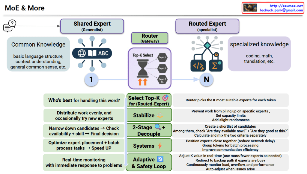
This diagram illustrates an advanced Mixture of Experts (MoE) model architecture.
Core Structure
1. Two Types of Experts
Shared Expert (Generalist)
Handles common knowledge: basic language structure, context understanding, general common sense
Applied universally to all tokens
Routed Expert (Specialist)
Handles specialized knowledge: coding, math, translation, etc.
Router selects the K most suitable experts for each token
2. Router (Gateway) Role
For each token, determines “Who’s best for handling this word?” by:
Selecting K experts out of N available specialists
Using Top-K selection mechanism
Key Optimization Techniques
Select Top-K 🎯
Chooses K most suitable routed experts
Distributes work evenly and occasionally tries new experts
Stabilize ⚖️
Prevents work from piling up on specific experts
Sets capacity limits and adds slight randomness
2-Stage Decouple 🔍
Creates a shortlist of candidate experts
Separately checks “Are they available now?” + “Are they good at this?”
Calculates and mixes the two criteria separately before final decision
Validates availability and skill before selection
Systems ⚡
Positions experts close together (reduces network delay)
Groups tokens for batch processing
Improves communication efficiency
Adaptive & Safety Loop 🔄
Adjusts K value in real-time (uses more/fewer experts as needed)
Redirects to backup path if experts are busy
Continuously monitors load, overflow, and performance
Auto-adjusts when issues arise
Purpose
This system enhances both efficiency and performance through:
Optimized expert placement
Accelerated batch processing
Real-time monitoring with immediate problem response
Summary
MoE & More combines generalist experts (common knowledge) with specialist experts (domain-specific skills), using an intelligent router to dynamically select the best K experts for each token. Advanced techniques like 2-stage decoupling, stabilization, and adaptive safety loops ensure optimal load balancing, prevent bottlenecks, and enable real-time adjustments for maximum efficiency. The result is a faster, more efficient, and more reliable AI system that scales intelligently.
This image contrasts traditional programming, where developers must explicitly code rules and logic (shown with a flowchart and a thoughtful programmer), with AI, where neural networks automatically learn patterns from large amounts of data (depicted with a network diagram and a smiling programmer). It illustrates the paradigm shift from manually defining rules to machines learning patterns autonomously from data.
Reduces FLOPs/costs while maintaining training/inference performance
Weights/Matmul in FP8 + FP32 Accumulation
Computes in lightweight units but sums precisely for critical totals (lower memory, bandwidth, compute, stable accuracy)
Predict Multiple Tokens at Once During Training
Delivers higher speed and accuracy boosts in benchmarks
2-tier Fat-Tree × Multiple Planes (separated per RDMA-NIC pair)
Provides inter-plane congestion isolation, resilience, and reduced cost/latency
Summary
DeepSeek-V3 represents a comprehensive optimization of large language models through innovations in attention mechanisms, expert routing, mixed-precision training, multi-token prediction, and network architecture. These techniques collectively address the three critical bottlenecks: memory, computation, and communication. The result is a highly efficient model capable of scaling to massive sizes while maintaining cost-effectiveness and performance.
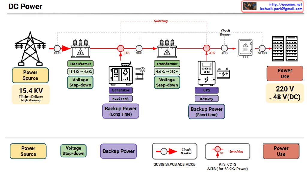
Generator reaches rated capacity and replaces main power
Generator power charges UPS + supplies load
Long-term operation with continuous fuel supply
Scenario 4: Generator Failure
Limited-time operation within UPS battery capacity
Priority operation for critical systems or graceful shutdown
5. Additional Protection and Control Devices
Supplementary devices for system stability and safety:
Circuit Breaker Hierarchy
GCB (Generator Circuit Breaker): Primary protection at reception point
VCB (Vacuum Circuit Breaker): Vacuum interruption, medium voltage protection
ACB (Air Circuit Breaker): Low voltage distribution panel protection
MCCB (Molded Case Circuit Breaker): Individual load protection
Role: Circuit interruption during overload or short circuit to protect equipment and personnel
Switching Devices
STS (Static Transfer Switch): High-speed transfer between main power ↔ generator
ATS (Automatic Transfer Switch): Automatic transfer between power sources ( UPS level)
ALTS (Automatic Load Transfer Switch): Automatic load transfer ( for 22.9kV class)
CCTS: Circuit breaker control and transfer system
Role: Automatic/immediate transfer to backup power during power failure
Switching Points (Red circle indicators)
Reception point, before/after transformers, backup power injection points
Critical points for power path changes and redundancy implementation
6. Key System Features
✅ Uninterruptible Power Supply: Three-stage protection with main power → generator → UPS ✅ Multi-stage Voltage Conversion: Ensures both transmission efficiency and usage safety ✅ Automated Backup Transfer: Automatic switching without human intervention ✅ Hierarchical Protection: Stage-by-stage circuit breakers prevent cascading failures ✅ Scalable Architecture: Modular configuration enables easy capacity expansion
Summary
This DC power system architecture ensures continuous, uninterrupted operation of mission-critical data center infrastructure through a sophisticated combination of redundant power sources, automated failover mechanisms, and multi-layered protection systems. The integration of long-term generator backup and short-term UPS battery systems creates a seamless power continuity solution that can handle any grid interruption scenario. The multi-stage voltage transformation (15.4KV → 6.6KV → 380V → 48V DC) optimizes both transmission efficiency and end-user safety while providing flexibility for diverse IT equipment requirements.
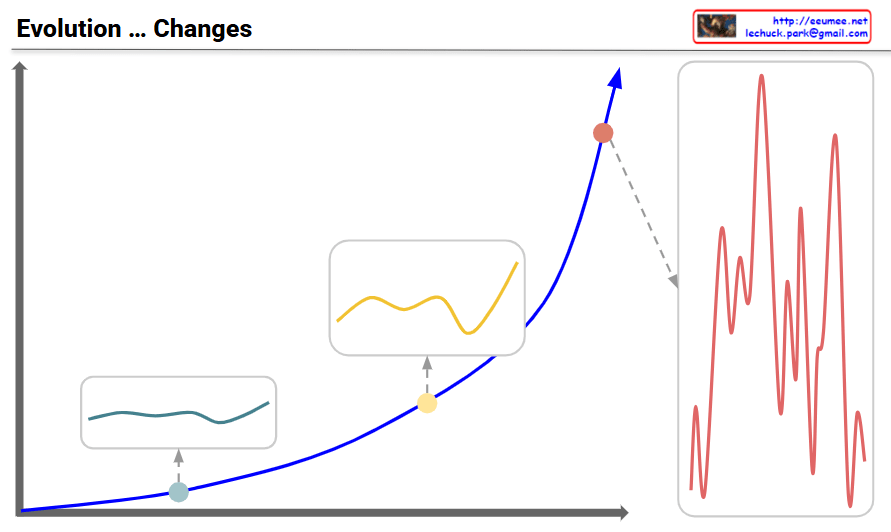
Evolution and Changes: Navigating Through Transformation
Overview:
Main Graph (Blue Curve)
Shows the pattern of evolutionary change transitioning from gradual growth to exponential acceleration over time
Three key developmental stages are marked with distinct points
Three-Stage Development Process:
Stage 1: Initial Phase (Teal point and box – bottom left)
Very gradual and stable changes
Minimal volatility with a flat curve
Evolutionary changes are slow and predictable
Response Strategy: Focus on incremental improvements and stable maintenance
Stage 2: Intermediate Phase (Yellow point and box – middle)
Fluctuations begin to emerge
Volatility increases but remains limited
Transitional period showing early signs of change
Response Strategy: Detect change signals and strengthen preparedness
Stage 3: Turbulent Phase (Red point and box on right – top)
Critical turning point where exponential growth begins
Volatility maximizes with highly irregular and large-amplitude changes
The red graph on the right details the intense and frequent fluctuations during this period
Characterized by explosive and unpredictable evolutionary changes
Response Imperative: Rapid and flexible adaptation is essential for survival in the face of high volatility and dramatic shifts
Key Message:
Evolution progresses through stable initial phases → emerging changes in the intermediate period → explosive transformation in the turbulent phase. During the turbulent phase, volatility peaks, making the ability to anticipate and actively respond critical for survival and success. Traditional stable approaches become obsolete; rapid adaptation and innovative transformation become essential.