LLM goes with Computing-Power-Cooling

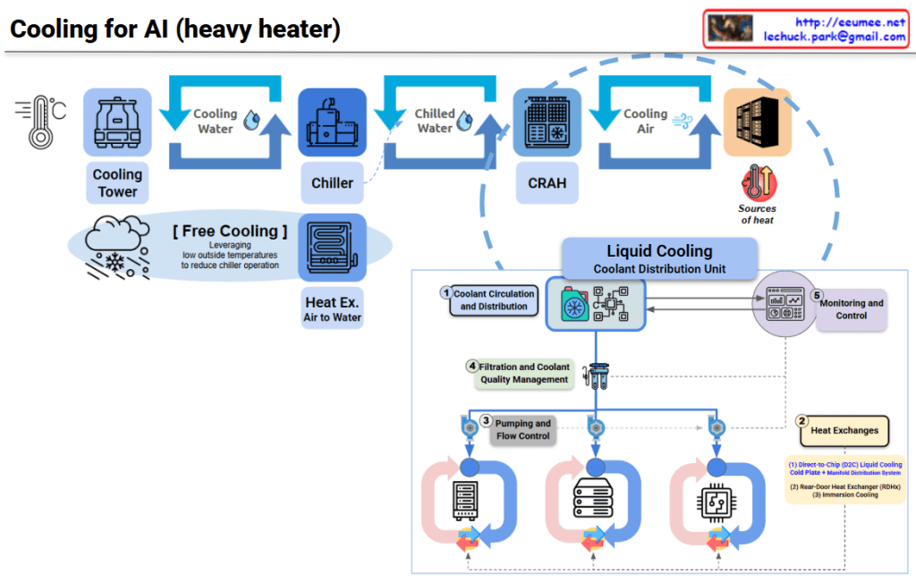
LLM’s Computing-Power-Cooling Relationship

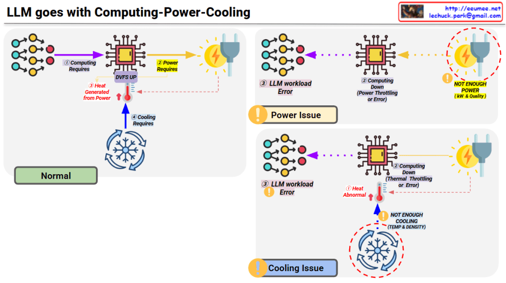
This diagram illustrates the technical architecture and potential issues that can occur when operating LLMs (Large Language Models).

Normal Operation (Top Left)

  1. Computing Requires – LLM workload is delivered to the processor
  2. Power Requires – Power supplied via DVFS (Dynamic Voltage and Frequency Scaling)
  3. Heat Generated – Heat is produced during computing processes
  4. Cooling Requires – Temperature management through proper cooling systems

Problem Scenarios

Power Issue (Top Right)

  • Symptom: Insufficient power (kW & Quality)
  • Results:
    • Computing performance degradation
    • Power throttling or errors
    • LLM workload errors

Cooling Issue (Bottom Right)

  • Symptom: Insufficient cooling (Temperature & Density)
  • Results:
    • Abnormal heat generation
    • Thermal throttling or errors
    • Computing performance degradation
    • LLM workload errors

Key Message

For stable LLM operations, the three elements of Computing-Power-Cooling must be balanced. If any one element is insufficient, it leads to system-wide performance degradation or errors. This emphasizes that AI infrastructure design must consider not only computing power but also adequate power supply and cooling systems together.


Summary

  • LLM operation requires a critical balance between computing, power supply, and cooling infrastructure.
  • Insufficient power causes power throttling, while inadequate cooling leads to thermal throttling, both resulting in workload errors.
  • Successful AI infrastructure design must holistically address all three components rather than focusing solely on computational capacity.

#LLM #AIInfrastructure #DataCenter #ThermalManagement #PowerManagement #AIOperations #MachineLearning #HPC #DataCenterCooling #AIHardware #ComputeOptimization #MLOps #TechInfrastructure #AIatScale #GreenAI

WIth Claude

Cooling for AI (heavy heater)

AI Data Center Cooling System Architecture Analysis

This diagram illustrates the evolution of data center cooling systems designed for high-heat AI workloads.

Traditional Cooling System (Top Section)

Three-Stage Cooling Process:

  1. Cooling Tower – Uses ambient air to cool water
  2. Chiller – Further refrigerates the cooled water
  3. CRAH (Computer Room Air Handler) – Distributes cold air to the server room

Free Cooling option is shown, which reduces chiller operation by leveraging low outside temperatures for energy savings.

New Approach for AI DC: Liquid Cooling System (Bottom Section)

To address extreme heat generation from high-density AI chips, a CDU (Coolant Distribution Unit) based liquid cooling system has been introduced.

Key Components:

① Coolant Circulation and Distribution

  • Direct coolant circulation system to servers

② Heat Exchanges (Two Methods)

  • Direct-to-Chip (D2C) Liquid Cooling: Cold plate with manifold distribution system directly contacting chips
  • Rear-Door Heat Exchanger (RDHx): Heat exchanger mounted on rack rear door (immersion cooling)

③ Pumping and Flow Control

  • Pumps and flow control for coolant circulation

④ Filtration and Coolant Quality Management

  • Maintains coolant quality and removes contaminants

⑤ Monitoring and Control

  • Real-time monitoring and cooling performance control

Critical Differences

Traditional Method: Air cooling → Indirect, suitable for low-density workloads

AI DC Method: Liquid cooling → Direct, high-efficiency, capable of handling high TDP (Thermal Design Power) of AI chips

Liquid has approximately 25x better heat transfer efficiency than air, making it effective for cooling AI accelerators (GPUs, TPUs) that generate hundreds of watts to kilowatt-level heat.


Summary:

  1. Traditional data centers use air-based cooling (Cooling Tower → Chiller → CRAH), suitable for standard workloads.
  2. AI data centers require liquid cooling with CDU systems due to extreme heat from high-density AI chips.
  3. Liquid cooling offers direct-to-chip heat removal with 25x better thermal efficiency than air, supporting kW-level heat dissipation.

#AIDataCenter #LiquidCooling #DataCenterInfrastructure #CDU #ThermalManagement #DirectToChip #AIInfrastructure #GreenDataCenter #HeatDissipation #HyperscaleComputing #AIWorkload #DataCenterCooling #ImmersionCooling #EnergyEfficiency #NextGenDataCenter

With Claude

DC Cooling (R)

Data Center Cooling System Core Structure

This diagram illustrates an integrated data center cooling system centered on chilled water/cooling water circulation and heat exchange.

Core Cooling Circulation Structure

Primary Loop: Cooling Water Loop

Cooling Tower → Cooling Water → Chiller → (Heat Exchange) → Cooling Tower

  • Cooling Tower: Dissipates heat from cooling water to atmosphere using outdoor air
  • Pump/Header: Controls cooling water pressure and flow rate through circulation pipes
  • Heat Exchange in Chiller: Cooling water exchanges heat with refrigerant to cool the refrigerant

Secondary Loop: Chilled Water Loop

Chiller → Chilled Water → CRAH → (Heat Exchange) → Chiller

  • Chiller: Generates chilled water (7-12°C) through compressor and refrigerant cycle
  • Pump/Header: Circulates chilled water to CRAH units and returns it back
  • Heat Exchange in CRAH: Chilled water exchanges heat with air to cool the air

Tertiary Loop: Cooling Air Loop

CRAH → Cooling Air → Servers → Hot Air → CRAH

  • CRAH (Computer Room Air Handler): Generates cooling air through water-to-air heat exchanger
  • FAN: Forces circulation of cooling air throughout server room
  • Heat Absorption: Air absorbs server heat and returns to CRAH

Heat Exchange Critical Points

Heat Exchange #1: Inside Chiller

  • Cooling Water ↔ Refrigerant: Transfers refrigerant heat to cooling water in condenser
  • Refrigerant ↔ Chilled Water: Absorbs heat from chilled water to refrigerant in evaporator

Heat Exchange #2: CRAH

  • Chilled Water ↔ Air: Transfers air heat to chilled water in water-to-air heat exchanger
  • Chilled water temperature rises → Returns to chiller

Heat Exchange #3: Server Room

  • Hot Air ↔ Servers: Air absorbs heat from servers
  • Temperature-increased air → Returns to CRAH

Energy Efficiency: Free Cooling

Low-Temperature Outdoor Air → Air-to-Water Heat Exchanger → Chilled Water Cooling → Reduced Chiller Load

  • Condition: When outdoor temperature is sufficiently low
  • Effect: Reduces chiller operation and compressor power consumption (up to 30-50%)
  • Method: Utilizes natural cooling through cooling tower or dedicated heat exchanger

Cooling System Control Elements

Cooling Basic Operations Components:

  • Cool Down: Controls water/air temperature reduction
  • Water Circulation: Adjusts flow rate through pump speed/pressure control
  • Heat Exchanges: Optimizes heat exchanger efficiency
  • Plumbing: Manages circulation paths and pressure loss

Heat Flow Summary

Server Heat → Air → CRAH (Heat Exchange) → Chilled Water → Chiller (Heat Exchange) → 
Cooling Water → Cooling Tower → Atmospheric Discharge


Summary

This system efficiently removes server heat to the outdoor atmosphere through three cascading circulation loops (air → chilled water → cooling water) and three strategic heat exchange points (CRAH, Chiller, Cooling Tower). Free cooling optimization reduces energy consumption by up to 50% when outdoor conditions permit. The integrated pump/header network ensures precise flow control across all loops for maximum cooling efficiency.


#DataCenterCooling #ChilledWater #CRAH #FreeCooling #HeatExchange #CoolingTower #ThermalManagement #DataCenterInfrastructure #EnergyEfficiency #HVACSystem #CoolingLoop #WaterCirculation #ServerCooling #DataCenterDesign #GreenDataCenter

With Claude