Data in AI DC

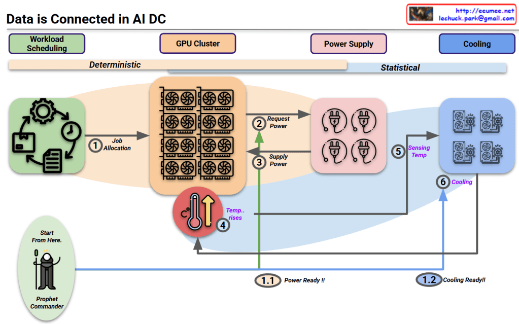
This image illustrates a data monitoring system for an AI data center server room. Titled “Data in AI DC Server Room,” it depicts the relationships between key elements being monitored in the data center.

The system consists of four main components, each with detailed metrics:

  1. GPU Workload – Right center
    • Computing Load: GPU utilization rate (%) and type of computational tasks (training vs. inference)
    • Power Consumption: Real-time power consumption of each GPU (W) – Example: NVIDIA H100 GPU consumes up to 700W
    • Workload Pattern: Periodicity of workload (peak/off-peak times) and predictability
    • Memory Usage: GPU memory usage patterns (e.g., HBM3 memory bandwidth usage)
  2. Power Infrastructure – Left
    • Power Usage: Real-time power output and efficiency of UPS, PDU, and transformers
    • Power Quality: Voltage, frequency stability, and power loss rate
    • Power Capacity: Types and proportions of supplied energy, ensuring sufficient power availability for current workload operations
  3. Cooling System – Right
    • Cooling Device Status: Air-cooling fan speed (RPM), liquid cooling pump flow rate (LPM), and coolant temperature (°C)
    • Environmental Conditions: Data center internal temperature, humidity, air pressure, and hot/cold zone temperatures – critical for server operations
    • Cooling Efficiency: Power Usage Effectiveness (PUE) and proportion of power consumed by the cooling system
  4. Server/Rack – Top center
    • Rack Power Density: Power consumption per rack (kW) – Example: GPU server racks range from 30 to 120 kW
    • Temperature Profile: Temperature (°C) of GPUs, CPUs, memory modules, and heat distribution
    • Server Status: Operational state of servers (active/standby) and workload distribution status

The workflow sequence indicated at the bottom of the diagram represents:

  1. ① GPU WORK: Initial execution of AI workloads – GPU computational tasks begin, generating system load
  2. ② with POWER USE: Increased power supply for GPU operations – Power demand increases with GPU workload, and power infrastructure responds accordingly
  3. ③ COOLING WORK: Cooling processes activated in response to heat generation
    • Sensing: Temperature sensors detect server and rack thermal conditions, monitoring hot/cold zone temperature differentials
    • Analysis: Analysis of collected temperature data, determining cooling requirements
    • Action: Adjustment of cooling equipment (fan speed, coolant flow rate, etc. automatically regulated)
  4. ④ SERVER OK: Maintenance of normal server operation through proper power supply and cooling – Temperature and power remain stable, allowing GPU workloads to continue running under optimal conditions

The arrows indicate data flow and interrelationships between systems, showing connections from power infrastructure to servers and from cooling systems to servers. This integrated system enables efficient and stable data center operation by detecting increased power demand and heat generation from GPU workloads, and adjusting cooling systems in real-time accordingly.

With Claude

Key Factors in DC

This image is a diagram showing the key components of a Data Center (DC).

The diagram visually represents the core elements that make up a data center:

  1. Building – Shown on the left with a building icon, representing the physical structure of the data center.
  2. Core infrastructure elements (in the central blue area):
    • Network – Data communication infrastructure
    • Computing – Servers and processing equipment
    • Power – Energy supply systems
    • Cooling – Temperature regulation systems
  3. The central orange circle represents server racks, which is connected to power supply units (transformers), cooling equipment, and network devices.
  4. Digital Service – Displayed on the right, representing the end services that all this infrastructure ultimately delivers.

This diagram illustrates how a data center flows from a physical building through core elements like network, computing, power, and cooling to ultimately provide digital services.

With Claude

Connected in AI DC

This diagram titled “Data is Connected in AI DC” illustrates the relationships starting from workload scheduling in an AI data center.

Key aspects of the diagram:

  1. The entire system’s interconnected relationships begin with workload scheduling.
  2. The diagram divides the process into two major phases:
    • Deterministic phase: Primarily concerned with power requirements that operate in a predictable, planned manner.
    • Statistical phase: Focused on cooling requirements, where predictions vary based on external environmental conditions.
  3. The “Prophet Commander” at the workload scheduling stage can predict/direct future requirements, allowing the system to prepare power (1.1 Power Ready!!) and cooling (1.2 Cooling Ready!!) in advance.
  4. Process flow:
    • Job allocation from workload scheduling to GPU cluster
    • GPUs request and receive power
    • Temperature rises due to operations
    • Cooling system detects temperature and activates cooling

This diagram illustrates the interconnected workflow in AI data centers, beginning with workload scheduling that enables predictive resource management. The process flows from deterministic power requirements to statistical cooling needs, with the “Prophet Commander” enabling proactive preparation of power and cooling resources. This integrated approach demonstrates how workload prediction can drive efficient resource allocation throughout the entire AI data center ecosystem.

With Claude

Data Explosion in Data Center

This image titled “Data Explosion in Data Center” illustrates three key challenges faced by modern data centers:

  1. Data/Computing:
    • Shows the explosive growth of data from computing servers to internet/cloud infrastructure and AI technologies.
    • Visualizes the exponential increase in data volume from 1X to 100X, 10,000X, and ultimately to 1,000,000,000X (one billion times).
    • Depicts how servers, computers, mobile devices, and global networks connect to massive data nodes, generating and processing enormous amounts of information.
  2. Power:
    • Addresses the increasing power supply requirements needed to support the data explosion in data centers.
    • Shows various energy sources including traditional power plants, wind turbines, solar panels, and battery storage systems to meet the growing energy demands.
    • Represents energy efficiency and sustainable power supply through a cyclical system indicated by green arrows.
  3. Cooling:
    • Illustrates the heat management challenges resulting from increased data processing and their solutions.
    • Explains the shift from traditional air cooling methods to more efficient server liquid cooling technologies.
    • Visualizes modern cooling solutions with blue circular arrows representing the cooling cycle.

This diagram comprehensively explains how the exponential growth of data impacts data center design and operations, particularly highlighting the challenges and innovations in power consumption and thermal management.

With Claude

AI Data Center : Power Req.

This image illustrates a diagram of power requirements and management for AI data centers:

Top Section – “More Power & Control”:

  • Diverse power sources: SMR (Small Modular Reactor), Reusable Energy (wind, solar), and ESS (Energy Storage System)
  • Power control system directing electricity from these various sources to the data center through “Power Control with Grid”
  • Integrated system for reliable and sustainable power supply

Bottom Section – “Optimization”:

  • Power distribution system through transformers and power supply units
  • Central control system for power routing
  • Load Balancing and Dynamic Power Management capabilities
  • Efficient power distribution to server racks based on GPU workload
  • “More Stable” indication emphasizing system reliability

This diagram highlights the importance of diversifying reliable power sources, efficient power control, and optimized power management according to GPU workload in AI data centers.

With Claude

Data Center Challenges

This diagram illustrates “Data Center Challenges” by visually explaining the key challenges faced by data centers and their potential solutions.

The central red circle highlights the main challenges:

  • “No Error” – representing reliable operations
  • “Cost down” – representing economic efficiency
  • Between these two goals, there typically exists a “trade-off” relationship

The “Optimization” section on the right breaks down the cost structure:

  1. “Power Cost”:
    • “Working” – representing IT power that can be optimized through “Green Coding”
    • “Cooling” – can be significantly optimized with “Using water” (liquid cooling) technologies
  2. “Labor Cost”:
    • Personnel costs that can be reduced through automation

The middle “Digital Automation” section shows:

  • “by Data” decision-making approaches
  • “With AI” methodologies

At the bottom, the final outcome shows:

  • “win win” – upward arrows and “Optimization” indicating that both goals can be achieved simultaneously

This diagram demonstrates how digital automation leveraging data and AI can help data centers achieve the seemingly conflicting goals of reliable operations and cost reduction simultaneously.

With Claude

Data Center NOW

This image shows a data center architecture diagram titled “Data Center Now” at the top. It illustrates the key components and flow of a modern data center infrastructure.

The diagram depicts:

  1. On the left side: An “Explosion of data” icon with data storage symbols, pointing to computing components with the note “More Computing is required”
  2. In the center: Server racks connected to various systems with colored lines indicating different connections (red, blue, green)
  3. On the right side: Several technology components illustrated with circular icons and labels:
    • “Software Defined” with a computer/gear icon
    • “AI & GPU” with neural network and GPU icons and note “Big power is required”
    • “Renewable Energy & Grid Power” with solar panel and wind turbine icons
    • “Optimized Cooling /w Using Water” with cooling system icon
    • “Enhanced Op System & AI Agent” with a robotic/AI system icon

The diagram shows how data flows through processing units and connects to different infrastructure elements, emphasizing modern data center requirements like increased computing power, AI capabilities, power management, and cooling solutions.

With Claude