Positional Encoding in Transformer Models
The Problem: Loss of Sequential Information
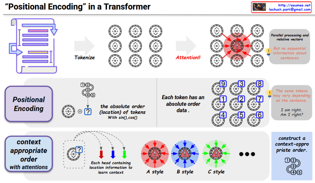
Transformer models use an attention mechanism that enables each token to interact with all other tokens in parallel, regardless of their positions in the sequence. While this parallel processing offers computational advantages, it comes with a significant limitation: the model loses all information about the sequential order of tokens. This means that without additional mechanisms, a Transformer cannot distinguish between sequences like “I am right” and “Am I right?” despite their different meanings.
The Solution: Positional Encoding
To address this limitation, Transformers implement positional encoding:
- Definition: Positional encoding adds position-specific information to each token’s embedding, allowing the model to understand sequence order.
- Implementation: The standard approach uses sinusoidal functions (sine and cosine) with different frequencies to create unique position vectors:
- For each position in the sequence, a unique vector is generated
- These vectors are calculated using sin() and cos() functions
- The position vectors are then added to the corresponding token embeddings
- Mathematical properties:
- Each position has a unique encoding
- The encodings have a consistent pattern that allows the model to generalize to sequence lengths not seen during training
- The relative positions of tokens can be expressed as a linear function of their encodings
Integration with Attention Mechanism
The combination of positional encoding with the attention mechanism enables Transformers to process tokens in parallel while maintaining awareness of their sequential relationships:
- Context-aware processing: Each attention head learns to interpret the positional information within its specific context.
- Multi-head flexibility: Different attention heads (A style, B style, C style) can focus on different aspects of positional relationships.
- Adaptive ordering: The model learns to construct context-appropriate ordering of tokens, enabling it to handle different linguistic structures and semantics.
Practical Impact
This approach allows Transformers to:
- Distinguish between sentences with identical words but different orders
- Understand syntactic structures that depend on word positions
- Process variable-length sequences effectively
- Maintain the computational efficiency of parallel processing while preserving sequential information
Positional encoding is a fundamental component that enables Transformer models to achieve state-of-the-art performance across a wide range of natural language processing tasks.
With Claude