Linux with ML

From Claude with some prompting
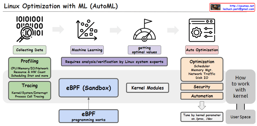
This image illustrates the process of utilizing Machine Learning (ML) and AutoML techniques for system optimization in Linux.

It starts with collecting data through profiling techniques that gather statistics on CPU, memory, I/O, network resource usage, hardware counters, scheduling information, etc. Tracing is also employed to capture kernel/system/interrupt events and process call traces.

The collected data is then used to train machine learning models. This step requires analysis and verification by Linux system experts.

The trained models help determine optimal values, which are then applied to optimize various system components such as the scheduler, memory management, network traffic, and disk I/O. Optimization can also target security and automation aspects.

The eBPF (Enhanced Berkeley Packet Filter) sandbox, situated in the center, allows safe execution within the kernel, enabling eBPF programs to interact with the kernel.

Kernel modules provide another way to implement optimization logic and integrate it directly into the kernel.

Finally, kernel parameters can be tuned from user space to perform optimizations.

In summary, the image depicts an AutoML-based process that leverages data collection, machine learning modeling, deriving optimal values, eBPF, kernel modules, and parameter tuning to automate system optimization in Linux across various kernel subsystems like the scheduler, memory management, network, and disk I/O.C

Foundation Model

From Claude with some prompting
This image depicts a high-level overview of a foundation model architecture. It consists of various components including a knowledge base, weight database (parameters), vector database (relative data), tuning module for making answers, inference module for generating answers, prompt tools, and an evaluation component for benchmarking.

The knowledge base stores structured information, while the weight and vector databases hold learnable parameters and relative data representations, respectively. The tuning and inference modules utilize these components to generate responses or make predictions. Prompt tools assist in forming inputs, and the evaluation component assesses the model’s performance.

This architectural diagram illustrates the core building blocks and data flow of a foundation model system, likely used for language modeling, knowledge representation, or other AI applications that require integrating diverse data sources and capabilities.

MTU concepts

From Claude with some prompting
This image explains the concept of Maximum Transfer Unit (MTU) in Ethernet networks. MTU refers to the largest size of an IP packet that can be transmitted in an Ethernet frame between network devices.

The image shows multiple Ethernet frames containing an IP packet inside. The MTU determines the maximum size of this IP packet that can fit within an Ethernet frame. Having a proper MTU size is important for efficient data transmission and avoiding fragmentation.

Some key points from the image:

  1. Ethernet frames encapsulate IP packets for transmission over the network.
  2. The MTU size represents the maximum IP packet size that can be carried in an Ethernet frame between devices.
  3. Serialized transmission occurs, allowing only one transmission at a time on the physical line.
  4. Large packets occupying the line for long periods can impact effective multiple transmissions (time-sharing).

New infra age

From Claude with some prompting
This image illustrates the surge in data and the advancement of AI technologies, particularly parallel processing techniques that efficiently handle massive amounts of data. As a result, there is a growing need for infrastructure technologies that can support such data processing capabilities. Technologies like big data processing, parallel processing, direct memory access, and GPU computing have evolved to meet this demand. The overall flow depicts the data explosion, the advancement of AI and parallel processing techniques, and the evolution of supporting infrastructure technologies.

DPU

From Claude with some prompting
The image illustrates the role of a Data Processing Unit (DPU) in facilitating seamless and delay-free data exchange between different hardware components such as the GPU, NVME (likely referring to an NVMe solid-state drive), and other devices.

The key highlight is that the DPU enables “Data Exchange Parallely without a Delay” and provides “Seamless” connectivity between these components. This means the DPU acts as a high-speed interconnect, allowing parallel data transfers to occur without any bottlenecks or latency.

The image emphasizes the DPU’s ability to provide a low-latency, high-bandwidth data processing channel, enabling efficient data movement and processing across various hardware components within a system. This seamless connectivity and delay-free data exchange are crucial for applications that require intensive data processing, such as data analytics, machine learning, or high-performance computing, where minimizing latency and maximizing throughput are critical.

==================

The key features of the DPU highlighted in the image are:

  1. Data Exchange Parallely: The DPU allows parallel data exchange without delay or bottlenecks, enabling seamless data transfer.
  2. Interconnection: The DPU interconnects different components like the GPU, NVME, and other devices, facilitating efficient data flow between them.

The DPU aims to provide a high-speed, low-latency data processing channel, enabling efficient data movement and computation between various hardware components in a system. This can be particularly useful in applications that require intensive data processing, such as data analytics, machine learning, or high-performance computing.Cop

Transformer

From Claude with some prompting
The image is using an analogy of transforming vehicles to explain the concept of the Transformer architecture in AI language models like myself.

Just like how a vehicle can transform into a robot by having its individual components work in parallel, a Transformer model breaks down the input data (e.g. text) into individual elements (tokens/words). These elements then go through a series of self-attention and feed-forward layers, processing the relationships between all elements simultaneously and in parallel.

This allows the model to capture long-range dependencies and derive contextual meanings, eventually transforming the input into a meaningful representation (e.g. understanding text, generating language). The bottom diagram illustrates this parallel and interconnected nature of processing in Transformers.

So in essence, the image draws a clever analogy between transforming vehicles and how Transformer models process and “transform” input data into contextualized representations through its parallelized and self-attentive computations.

Data Analysis Platform

From Claude with some prompting
The given image illustrates the overall architecture of a data analysis platform. At the data collecting stage, data is gathered from actual equipment or systems (servers). Protocols like Kafka, SNMP, and OPC are used for data streaming or polling.

The ‘select’ part indicates selecting specific data from the entire collected dataset. Based on the configuration information of the actual equipment, only the data of interest can be selectively collected, allowing the expansion of the data collection scope.

The selected data is stored in a data storage system and then loaded into an SQL database through an ETL (Extract, Transform, Load) process. Afterward, flexible data analysis is enabled using tools like ETL, ansi-SQL, and visualization.

Performance metrics for the entire process are provided numerically, and analysis tasks can be performed through the user interface of the data analysis platform.

The key aspects highlighted are the collection of data from actual equipment/systems, selective data collection based on equipment configuration, data storage, ETL process, SQL database, analysis tools (ETL, SQL, visualization), performance metrics, and the analysis platform user interface.