LMM Operation

LLM Operations System Analysis

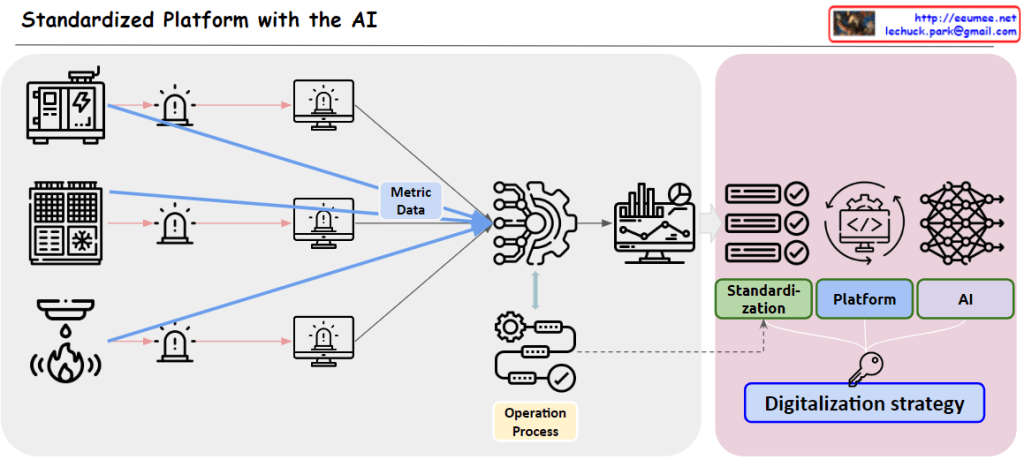
This diagram illustrates the architecture of an LLM Operations (LLMOps) system, demonstrating how Large Language Models are deployed and operated in industrial settings.

Key Components and Data Flow

1. Data Input Sources (3 Categories)

  • Facility: Digitized sensor data that gets detected and generates alert/event logs
  • Manual: Equipment manuals and technical documentation
  • Experience: Operational manuals including SOP/MOP/EOP (Standard/Maintenance/Emergency Operating Procedures)

2. Central Processing System

  • RAG (Retrieval-Augmented Generation): A central hub that integrates and processes all incoming data
  • Facility data is visualized through metrics and charts for monitoring purposes

3. LLM Operations

  • The central LLM synthesizes all information to provide intelligent operational support
  • Interactive interface enables user communication and queries

4. Final Output and Control

  • Dashboard for data visualization and monitoring
  • AI chatbot for real-time operational assistance
  • Operator Control: The bottom section shows checkmark (✓) and X-mark (✗) buttons along with an operator icon, indicating that final decision-making authority remains with human operators

System Characteristics

This system represents a smart factory solution that integrates AI into traditional industrial operations, providing comprehensive management from real-time data monitoring to operational manual utilization.

The key principle is that while AI provides comprehensive analysis and recommendations, the final operational decisions and approvals still rest with human operators. This is clearly represented through the operator icon and approval/rejection buttons at the bottom of the diagram.

This demonstrates a realistic and desirable AI operational model that emphasizes safety, accountability, and the importance of human judgment in unpredictable situations.

With Claude

Metric Monitoring Strategy

With a Claude’s Help
the Metric Monitoring System diagram:

  1. Data Hierarchy (Top)
  • Raw Metric: Unprocessed source data
  • Made Metric: Combined metrics from related data
  • Multi-data: Interrelated metrics sets
  1. Analysis Pipeline (Bottom)

Progressive Stages:

  • Basic: Change detection, single value, delta analysis
  • Intermediate: Basic statistics (avg/min/max), standard deviation
  • Advanced: Z-score/IQR
  • ML-based: ARIMA/Prophet, LSTM, AutoEncoder

Key Features:

  • Computing power increases with complexity (left to right)
  • Correlation and dependency analysis integration
  • Two-tier ML approach: ML1 (prediction), ML2 (pattern recognition)

Implementation Benefits:

  • Resource optimization through staged processing
  • Scalable analysis from basic monitoring to predictive analytics
  • Comprehensive anomaly detection
  • Flexible system adaptable to different monitoring needs

The system provides a complete framework from simple metric tracking to advanced machine learning-based analysis, enabling both reactive and predictive monitoring capabilities.

Additional Values:

  • Early warning system potential
  • Root cause analysis support
  • Predictive maintenance enablement
  • Resource allocation optimization
  • System health forecasting

This architecture supports both operational monitoring and strategic analysis needs while maintaining resource efficiency through its graduated approach to data processing.Copy

Data & Decision

with a Claude’s Help
This diagram illustrates the process of converting real-world analog values into actionable decisions through digital systems:

  1. Input Data Characteristics
  • Metric Value: Represents real-world analog values that are continuous variables with high precision. While these can include very fine digital measurements, they are often too complex for direct system processing.
  • Examples: Temperature, velocity, pressure, and other physical measurements
  1. Data Transformation Process
  • Through ‘Sampling & Analysis’, continuous Metric Values are transformed into meaningful State Values.
  • This represents the process of simplifying and digitalizing complex analog signals.
  1. State Value Characteristics and Usage
  • Converts to discrete variables with high readability
  • Examples: Temperature becomes ‘High/Normal/Low’, speed becomes ‘Over/Normal/Under’
  • These State values are much more programmable and easier to process in systems
  1. Decision Making and Execution
  • The simplified State values enable clear decision-making (Easy to Decision)
  • These decisions can be readily implemented through Programmatic Works
  • Leads to automated execution (represented by “DO IT!”)

The key concept here is the transformation of complex real-world measurements into clear, discrete states that systems can understand and process. This conversion facilitates automated decision-making and execution. The diagram emphasizes that while Metric Values provide high precision, State Values are more practical for programmatic implementation and decision-making processes.

The flow shows how we bridge the gap between analog reality and digital decision-making by converting precise but complex measurements into actionable, programmable states. This transformation is essential for creating reliable and automated decision-making systems.

Metric

From Claude with some prompting
the diagram focuses on considerations for a single metric:

  1. Basic Metric Components
  • Point: Measurement point (where it’s collected)
  • Number: Actual measured values (4,5,5,8,4,3,4)
  • Precision: Accuracy of measurement
  1. Time Characteristics
  • Time Series Data: Collected in time series format
  • Real Time Streaming: Real-time streaming method
  • Sampling Rate: How many measurements per second
  • Resolution: Time resolution
  1. Change Detection
  • Changes: Value variations
    • Range: Acceptable range
    • Event: Notable changes
  • Delta: Change from previous value (new-old)
  • Threshold: Threshold settings
  1. Quality Management
  • No Data: Missing data state
  • Delay: Data latency state
  • With All Metrics: Correlation with other metrics
  1. Pattern Analysis
  • Long Time Pattern: Long-term pattern existence
  • Machine Learning: Pattern-based learning potential

In summary, this diagram comprehensively shows key considerations for a single metric:

  • Collection method (how to gather)
  • Time characteristics (how frequently to collect)
  • Change detection (what changes to note)
  • Quality management (how to ensure data reliability)
  • Utilization approach (how to analyze and use)

These aspects form the fundamental framework for understanding and implementing a single metric in a monitoring system.

Time Series Data

From Claude with some prompting

  1. Raw Time Series Data:
    • Data Source: Sensors or meters operating 24/7, 365 days a year
    • Components: a. Point: The data point being measured b. Metric: The measurement value for each point c. Time: When the data was recorded
    • Format: (Point, Value, Time)
    • Additional Information: a. Config Data: Device name, location, and other setup information b. Tag Info: Additional metadata or classification information for the data
    • Characteristics:
      • Continuously updated based on status changes
      • Automatically changes over time
  2. Processed Time Series Data (2nd logical Data):
    • Processing Steps: a. ETL (Extract, Transform, Load) operations b. Analysis of correlations between data points (Point A and Point B) c. Data processing through f(x) function
      • Creating formulas through correlations using experience and AI learning
    • Result:
      • Generation of new data points
      • Includes original point, related metric, and time information
    • Characteristics:
      • Provides more meaningful and correlated information than raw data
      • Reflects relationships and influences between data points
      • Usable for more complex analysis and predictions

Through this process, Raw Time Series Data is transformed into more useful and insightful Processed Time Series Data. This aids in understanding data patterns and predicting future trends.

Standardized Platform with the AI

From Claude with some prompting
This image illustrates a “Standardized Platform with the AI”. Here’s a breakdown of the key components and processes:

  1. Left side: Various devices or systems (generator, HVAC system, fire detector, etc.) are shown. Each device is connected to an alarm system and a monitoring screen.
  2. Center: “Metric Data” from these devices is sent to a central gear-shaped icon, representing a data processing system.
  3. Upper right: The processed data is displayed on a dashboard or analytics screen.
  4. Lower right: There’s a section labeled “Operation Process”, indicating management or optimization of operational processes.
  5. Far right: Boxes representing the system’s components:
    • “Standardization”
    • “Platform”
    • “AI”
  6. Bottom: “Digitalization strategy” serves as the foundation for the entire system.

This diagram visualizes a digital transformation strategy that collects data from various systems and devices, processes it using AI on a standardized platform, and uses this to optimize and manage operations.

The flow shows how raw data from different sources is standardized, processed, and utilized to create actionable insights and improve operational efficiency, all underpinned by a comprehensive digitalization strategy.

Trend & Prediction

From Claude with some prompting
The image presents a “Trend & Predictions” process, illustrating a data-driven prediction system. The key aspect is the transition from manual validation to automation.

  1. Data Collection & Storage: Digital data is gathered from various sources and stored in a database.
  2. Manual Selection & Validation: a. User manually selects which metric (data) to use b. User manually chooses which AI model to apply c. Analysis & Confirmation using selected data and model
  3. Transition to Automation:
    • Once optimal metrics and models are confirmed in the manual validation phase, the system learns and switches to automation mode. a. Automatically collects and processes data based on selected metrics b. Automatically applies validated models c. Applies pre-set thresholds to prediction results d. Automatically detects and alerts on significant predictive patterns or anomalies based on thresholds

The core of this process is combining user expertise with system efficiency. Initially, users directly select metrics and models, validating results to “educate” the system. This phase determines which data is meaningful and which models are accurate.

Once this “learning” stage is complete, the system transitions to automation mode. It now automatically collects, processes data, and generates predictions using user-validated metrics and models. Furthermore, it applies preset thresholds to automatically detect significant trend changes or anomalies.

This enables the system to continuously monitor trends, providing alerts to users whenever important changes are detected. This allows users to respond quickly, enhancing both the accuracy of predictions and the efficiency of the system.