Workload trigger

From Claude with some prompting
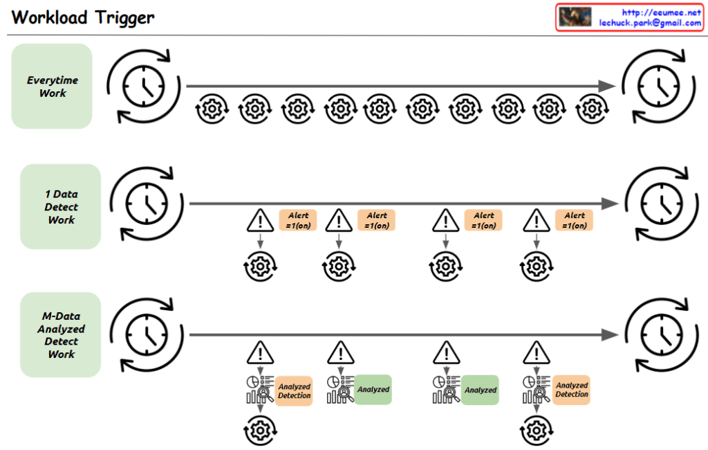
The image appears to be a diagram illustrating a “Workload Trigger” process. It shows three main stages of work:

  1. “Everytime Work”: This stage indicates work that is performed at a regular interval, represented by the repeating gear symbols.
  2. “1 Data Detect Work”: This stage shows data detection work that triggers alerts based on certain conditions, represented by the alert symbols.
  3. “M-Data Analyzed Detect Work”: This stage shows data analysis work that also triggers alerts based on the analysis results, represented by the analyzed detection symbols.

The overall flow of the diagram moves from left to right, with the work cycling through the three main stages. The timing of the work cycles is indicated by the clocks at the start and end of each stage.

The diagram seems to be illustrating some kind of automated monitoring or analysis workflow that triggers alerts based on the detection of certain data patterns or conditions.

log with the LLM

From Claude with some prompting
This image represents an “Alarm log with the LLM” system. The key components and functionality are as follows:

  1. NMS (Network Management System): A monitoring system that collects and displays alarm data.
  2. Text-based Event-driven Syslog: A system that logs events and alarm data in real-time text format. Syslog provides immediate data that is easily collected from existing environments.
  3. DCIM (Data Center Infrastructure Management): A system that manages the physical infrastructure of a data center, including alarms and monitoring.
  4. AI: An artificial intelligence component that utilizes a Large Language Model (LLM) for learning.
  5. 1-minute alarm analysis results and solutions: From a real-time monitoring perspective, this analyzes immediate alarm situations and provides solutions.
  6. 1-month alarm analysis: This long-term analysis of alarm data identifies anticipated problems. The analysis results can be used to provide a chatbot-based status query and response environment.

Overall, this system can provide powerful alarm management capabilities through real-time monitoring and predictive analysis.

Lechuck History

From Claude with some prompting
“Lechuck History” diagram demonstrates the following technical career progression:

  1. “with Computer” section:
    • Advanced from C-based programming to system programming, O&M solutions, and network programming
    • Possess deep understanding of Linux kernel, RTOS, and TCP/IP stack
    • Performed “Single-Handedly A to Z” tasks in web service analysis/monitoring
    • Grew into the role of a software engineer
  2. “with People” section:
    • Gained experience in large ISP data centers, system management, large-scale network operations management, and CDN development/management
    • Developed skills to optimize and maximize existing system infrastructure
    • Created new service solutions including D/C business web portals, NMS big-data, DCIM, packet analysis customer solutions, and data analysis platforms
    • Managed “Big DC Op. System Design & DevOps”, demonstrating ability to handle customer-facing roles and collaborate with various partners

Additional key competencies:

  1. Maintain continuous interest in new technologies
  2. Possess the ability to quickly learn based on a solid understanding of fundamentals
  3. Currently enjoy learning cutting-edge technologies including AI and Quantum computing

This career path and skill set demonstrate the profile of a professional who continuously grows and pursues innovation in a rapidly changing technological environment.

A series of decisions

From Claude with some prompting
The image depicts a diagram titled “A series of decisions,” illustrating a data processing and analysis workflow. The main stages are as follows:

  1. Big Data: The starting point for data collection.
  2. Gathering Domains by Searching: This stage involves searching for and collecting relevant data.
  3. Verification: A step to validate the collected data.
  4. Database: Where data is stored and managed. This stage includes “Select Betters” for data refinement.
  5. ETL (Extract, Transform, Load): This process involves extracting, transforming, and loading data, with a focus on “Select Combinations.”
  6. AI Model: The stage where artificial intelligence models are applied, aiming to find a “More Fit AI Model.”

Each stage is accompanied by a “Visualization” icon, indicating that data visualization plays a crucial role throughout the entire process.

At the bottom, there’s a final step labeled “Select Results with Visualization,” suggesting that the outcomes of the entire process are selected and presented through visualization techniques.

Arrows connect these stages, showing the flow from Big Data to the AI Model, with “Select Results” arrows feeding back to earlier stages, implying an iterative process.

This diagram effectively illustrates the journey from raw big data to refined AI models, emphasizing the importance of decision-making and selection at each stage of the data processing and analysis workflow.

Integration DC

From Claude with some prompting
This diagram depicts an architecture for data center (DC) infrastructure expansion and integrated operations management across multiple sites. The key features include:

  1. Integration and monitoring of comprehensive IT infrastructure at the site level, including networks, servers, storage, power, cooling, and security.
  2. Centralized management of infrastructure status, events, and alerts from each site through the “Integration & Alert Main” system.
  3. The central integration system collects diverse data from sites and performs data integration and analysis through the “Service Integration” layer:
    • Data integration, private networking, synchronization, and analysis of new applications
    • Inclusion of advanced AI-based data analytics capabilities
  4. Leveraging analysis results to support infrastructure system optimization and upgrade decisions at each site.
  5. Improved visibility, control, and efficiency over the entire DC infrastructure through centralized monitoring and integration.

This architecture enables unified management of distributed infrastructure resources in an expanded DC environment and enhances operational efficiency through data-driven optimization.

By consolidating monitoring and integrating data analytics, organizations can gain comprehensive insights, make informed decisions, and streamline operations across their distributed data center footprint.

DC Data Collecting Performance Factors

From Claude with some prompting
This image conceptually illustrates various factors that can affect the performance of DC data collection. The main components include the facility generating the data, the facility network, PLC/DDC converters, an integration network, and the final collection/analysis system.

Factors that can impact data collection performance include the data generation rate, CPU performance, bandwidth limitations of the network medium, network topology, protocols used (such as TCP/IP and SNMP), input/output processing performance, and program logic.

The diagram systematically outlines the overall flow of the DC data collection process and the performance considerations at each stage. It covers elements like the facility, network infrastructure, data conversion, integration, and final collection/analysis.

By mapping out these components and potential bottlenecks, the image can aid in the design and optimization of data collection systems. It provides a comprehensive overview of the elements that need to be accounted for to ensure efficient data gathering performance.


Data Analysis Platform

From Claude with some prompting
The given image illustrates the overall architecture of a data analysis platform. At the data collecting stage, data is gathered from actual equipment or systems (servers). Protocols like Kafka, SNMP, and OPC are used for data streaming or polling.

The ‘select’ part indicates selecting specific data from the entire collected dataset. Based on the configuration information of the actual equipment, only the data of interest can be selectively collected, allowing the expansion of the data collection scope.

The selected data is stored in a data storage system and then loaded into an SQL database through an ETL (Extract, Transform, Load) process. Afterward, flexible data analysis is enabled using tools like ETL, ansi-SQL, and visualization.

Performance metrics for the entire process are provided numerically, and analysis tasks can be performed through the user interface of the data analysis platform.

The key aspects highlighted are the collection of data from actual equipment/systems, selective data collection based on equipment configuration, data storage, ETL process, SQL database, analysis tools (ETL, SQL, visualization), performance metrics, and the analysis platform user interface.