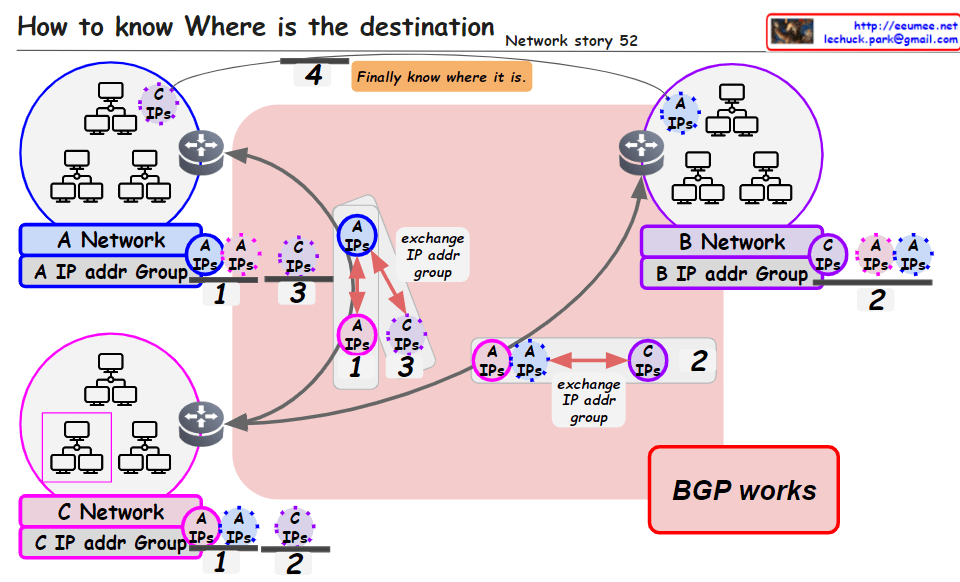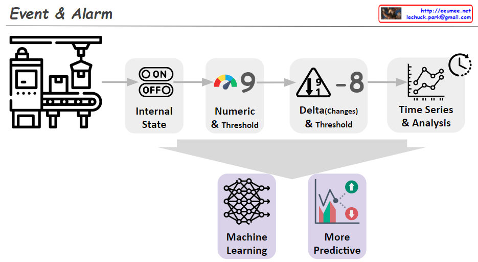
From DALL-E with some prompting
The image illustrates the progressive stages of detecting alarm events through data analysis. Here’s a summary:
- Internal State: It shows a machine with an ‘ON/OFF’ state, indicating whether the equipment is currently operating.
- Numeric & Threshold: A numeric value is monitored against a set threshold, which can trigger an alert if exceeded.
- Delta (Changes) & Threshold: A representation of an alert triggered by significant changes or deviations in the equipment’s performance, as compared to a predefined threshold.
- Time Series & Analysis: This suggests that analyzing time-series data can identify trends and forecast potential issues.
- Machine Learning: Depicts the use of machine learning to interpret data and build predictive models.
- More Predictive: The final stage shows the use of machine learning insights to anticipate future events, leading to a more sophisticated alarm system.
Overall, the image conveys the evolution of alarm systems from basic monitoring to advanced prediction using machine learning.