Peak Shaving


“Power – Peak Shaving” Strategy

The image illustrates a 5-step process for a ‘Peak Shaving’ strategy designed to maximize power efficiency in data centers. Peak shaving is a technique used to reduce electrical load during periods of maximum demand (peak times) to save on electricity costs and ensure grid stability.

1. IT Load & ESS SoC Monitoring

This is the data collection and monitoring phase to understand the current state of the system.

  • Grid Power: Monitoring the maximum power usage from the external power grid.
  • ESS SoC/SoH: Checking the State of Charge (SoC) and State of Health (SoH) of the Energy Storage System (ESS).
  • IT Load (PDU): Measuring the actual load through Power Distribution Units (PDUs) at the server rack level.
  • LLM/GPU Workload: Monitoring the real-time workload of AI models (LLM) and GPUs.

2. ML-based Peak Prediction

Predicting future power demand based on the collected data.

  • Integrated Monitoring: Consolidating data from across the entire infrastructure.
  • Machine Learning Optimization: Utilizing AI algorithms to accurately predict when power peaks will occur and preparing proactive responses.

3. Peak Shaving Via PCS (Power Conversion System)

Utilizing physical energy storage hardware to distribute the power load.

  • Pre-emptive Analysis & Preparation: Determining the “Time to Charge.” The system charges the batteries when electricity rates are low.
  • ESS DC Power: During peak times, the stored Direct Current (DC) in the ESS is converted to Alternating Current (AC) via the PCS to supplement the power supply, thereby reducing reliance on the external grid.

4. Job Relocation (K8s/Slurm)

Adjusting the scheduling of IT tasks based on power availability.

  • Scheduler Decision Engine: Activated when a peak time is detected or when ESS battery levels are low.
  • Job Control: Lower priority jobs are queued or paused, and compute speeds are throttled (power suppressed) to minimize consumption.

5. Parameter & Model Optimization

The most advanced stage, where the efficiency of the AI models themselves is optimized.

  • Real-time Batch Size Adjustment: Controlling throughput to prevent sudden power spikes.
  • Large Model -> sLLM (Lightweight): Transitioning to smaller, lightweight Large Language Models (sLLM) to reduce GPU power consumption without service downtime.

Summary

The core message of this diagram is that High-Quality/High-Resolution Data is the foundation for effective power management. By combining hardware solutions (ESS/PCS), software scheduling (K8s/Slurm), and AI model optimization (sLLM), a data center can significantly reduce operating expenses (OPEX) and ultimately increase profitability (Make money) through intelligent peak shaving.


#AI_DC #PowerControl #DataCenter #EnergyEfficiency #PeakShaving #GreenIT #MachineLearning #ESS #AIInfrastructure #GPUOptimization #Sustainability #TechInnovation
Numeric Data Processing


Architecture Overview

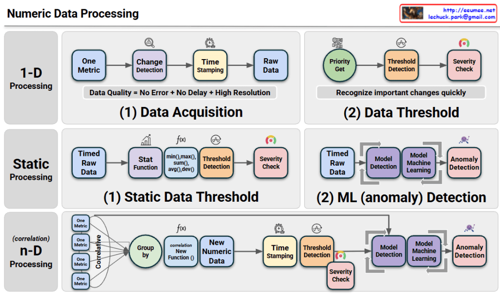
The diagram illustrates a tiered approach to Numeric Data Processing, moving from simple monitoring to advanced predictive analytics:

  • 1-D Processing (Real-time Detection): This layer focuses on individual metrics. It emphasizes high-resolution data acquisition with precise time-stamping to ensure data quality. It uses immediate threshold detection to recognize critical changes as they happen.
  • Static Processing (Statistical & ML Analysis): This stage introduces historical context. It applies statistical functions (like averages and deviations) to identify trends and uses Machine Learning (ML) models to detect anomalies that simple thresholds might miss.
  • n-D Processing (Correlative Intelligence): This is the most sophisticated layer. It groups multiple metrics to find correlations, creating “New Numeric Data” (synthetic metrics). By analyzing the relationship between different data points, it can identify complex root causes in highly interleaved systems.

Summary

  1. The framework transitions from reactive 1-D monitoring to proactive n-D correlation, enhancing the depth of system observability.
  2. It integrates statistical functions and machine learning to filter noise and identify true anomalies based on historical patterns rather than just fixed limits.
  3. The ultimate goal is to achieve high-fidelity data processing that enables automated severity detection and complex pattern recognition across multi-dimensional datasets.

#DataProcessing #AIOps #MachineLearning #Observability #Telemetry #SystemArchitecture #AnomalyDetection #DigitalTwin #DataCenterOps #InfrastructureMonitoring

With Gemini

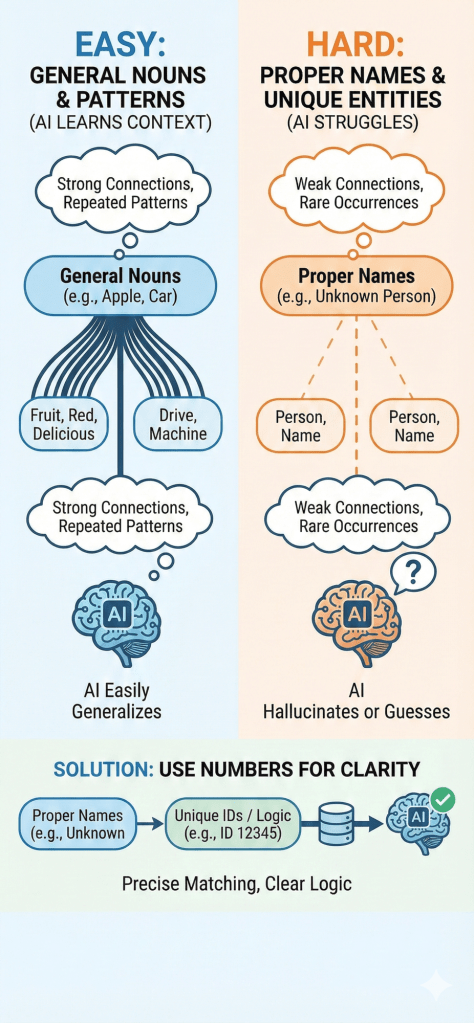
AI Processing Logic: Patterns vs. Unique Entities

This infographic illustrates the fundamental difference in how AI processes language. It shows that AI excels at understanding General Nouns (like “apple” or “car”) because they are built on strong, repeated contextual patterns. In contrast, AI struggles with Proper Nouns (like specific names) due to weak connections and a lack of context, often leading to hallucinations. The visual suggests a solution: converting unique entities into Numbers or IDs, which offer the clear logic and precision that AI models prefer over ambiguous text.

With Gemini

MPFT: Multi-Plane Fat-Tree for Massive Scale and Cost Efficiency


MPFT: Multi-Plane Fat-Tree for Massive Scale and Cost Efficiency

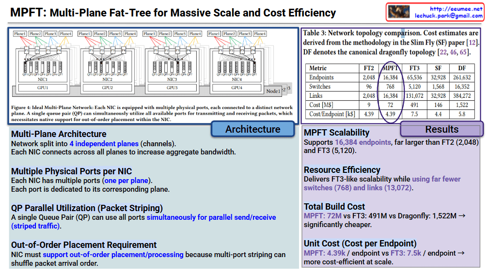
1. Architecture Overview (Blue Section)

The core innovation of MPFT lies in parallelizing network traffic across multiple independent “planes” to maximize bandwidth and minimize hardware overhead.

  • Multi-Plane Architecture: The network is split into 4 independent planes (channels).
  • Multiple Physical Ports per NIC: Each Network Interface Card (NIC) is equipped with multiple ports—one for each plane.
  • QP Parallel Utilization (Packet Striping): A single Queue Pair (QP) can utilize all available ports simultaneously. This allows for striped traffic, where data is spread across all paths at once.
  • Out-of-Order Placement: Because packets travel via different planes, they may arrive in a different order than they were sent. Therefore, the NIC must natively support out-of-order processing to reassemble the data correctly.

2. Performance & Cost Results (Purple Section)

The table compares MPFT against standard topologies like FT2/FT3 (Fat-Tree), SF (Slim Fly), and DF (Dragonfly).

MetricMPFTFT3Dragonfly (DF)
Endpoints16,38465,536261,632
Switches7685,12016,352
Total Cost$72M$491M$1,522M
Cost per Endpoint$4.39k$7.5k$5.8k
  • Scalability: MPFT supports 16,384 endpoints, which is significantly higher than a standard 2-tier Fat-Tree (FT2).
  • Resource Efficiency: It achieves high scalability while using far fewer switches (768) and links compared to the 3-tier Fat-Tree (FT3).
  • Economic Advantage: At $4.39k per endpoint, it is one of the most cost-efficient models for large-scale data centers, especially when compared to the $7.5k cost of FT3.

Summary

MPFT is presented as a “sweet spot” solution for AI/HPC clusters. It provides the high-speed performance of complex 3-tier networks but keeps the cost and hardware complexity closer to simpler 2-tier systems by using multi-port NICs and traffic striping.


#NetworkArchitecture #DataCenter #HighPerformanceComputing #GPU #AITraining #MultiPlaneFatTree #MPFT #NetworkingTech #ClusterComputing #CloudInfrastructure

Parallelism (1) – Data , Expert

Parallelism Comparison: Data Parallelism vs Expert Parallelism

This image compares two major parallelization strategies used for training large language models (LLMs).

Left: Data Parallelism

Structure:

  • Data is divided into multiple batches from the database
  • Same complete model is replicated on each GPU
  • Each GPU independently processes different data batches
  • Results are aggregated to generate final output

Characteristics:

  • Scaling axis: Number of batches/samples
  • Pattern: Full model copy on each GPU, dense training
  • Communication: Gradient All-Reduce synchronization once per step
  • Advantages: Simple and intuitive implementation
  • Disadvantages: Model size must fit in single GPU memory

Right: Expert Parallelism

Structure:

  • Data is divided by layers
  • Tokens are distributed to appropriate experts through All-to-All network and router
  • Different expert models (A, B, C) are placed on each GPU
  • Parallel processing at block/thread level in GPU pool

Characteristics:

  • Scaling axis: Number of experts
  • Pattern: Sparse structure – only few experts activated per token
  • Goal: Maintain large capacity while limiting FLOPs per token
  • Communication: All-to-All token routing
  • Advantages: Can scale model capacity significantly (MoE – Mixture of Experts architecture)
  • Disadvantages: High communication overhead and complex load balancing

Key Differences

AspectData ParallelismExpert Parallelism
Model DivisionFull model replicationModel divided into experts
Data DivisionBatch-wiseLayer/token-wise
Communication PatternGradient All-ReduceToken All-to-All
ScalabilityProportional to data sizeProportional to expert count
EfficiencyDense computationSparse computation (conditional activation)

These two approaches are often used together in practice, enabling ultra-large-scale model training through hybrid parallelization strategies.


Summary

Data Parallelism replicates the entire model across GPUs and divides the training data, synchronizing gradients after each step – simple but memory-limited. Expert Parallelism divides the model into specialized experts and routes tokens dynamically, enabling massive scale through sparse activation. Modern systems combine both strategies to train trillion-parameter models efficiently.

#MachineLearning #DeepLearning #LLM #Parallelism #DistributedTraining #DataParallelism #ExpertParallelism #MixtureOfExperts #MoE #GPU #ModelTraining #AIInfrastructure #ScalableAI #NeuralNetworks #HPC

LLM goes with Computing-Power-Cooling

LLM’s Computing-Power-Cooling Relationship

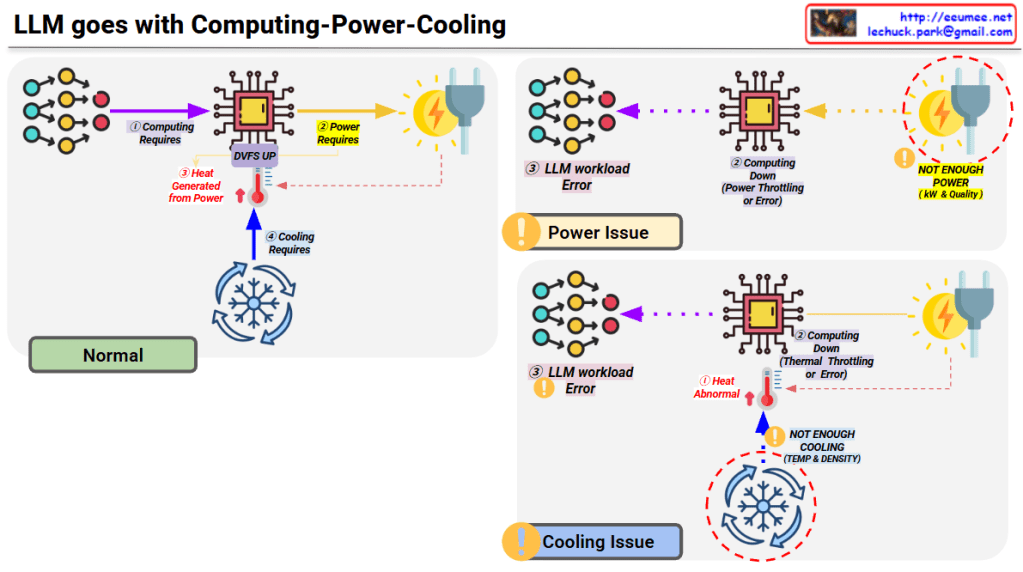
This diagram illustrates the technical architecture and potential issues that can occur when operating LLMs (Large Language Models).

Normal Operation (Top Left)

  1. Computing Requires – LLM workload is delivered to the processor
  2. Power Requires – Power supplied via DVFS (Dynamic Voltage and Frequency Scaling)
  3. Heat Generated – Heat is produced during computing processes
  4. Cooling Requires – Temperature management through proper cooling systems

Problem Scenarios

Power Issue (Top Right)

  • Symptom: Insufficient power (kW & Quality)
  • Results:
    • Computing performance degradation
    • Power throttling or errors
    • LLM workload errors

Cooling Issue (Bottom Right)

  • Symptom: Insufficient cooling (Temperature & Density)
  • Results:
    • Abnormal heat generation
    • Thermal throttling or errors
    • Computing performance degradation
    • LLM workload errors

Key Message

For stable LLM operations, the three elements of Computing-Power-Cooling must be balanced. If any one element is insufficient, it leads to system-wide performance degradation or errors. This emphasizes that AI infrastructure design must consider not only computing power but also adequate power supply and cooling systems together.


Summary

  • LLM operation requires a critical balance between computing, power supply, and cooling infrastructure.
  • Insufficient power causes power throttling, while inadequate cooling leads to thermal throttling, both resulting in workload errors.
  • Successful AI infrastructure design must holistically address all three components rather than focusing solely on computational capacity.

#LLM #AIInfrastructure #DataCenter #ThermalManagement #PowerManagement #AIOperations #MachineLearning #HPC #DataCenterCooling #AIHardware #ComputeOptimization #MLOps #TechInfrastructure #AIatScale #GreenAI

WIth Claude

The Perfect Paradox

The Perfect Paradox – Analysis

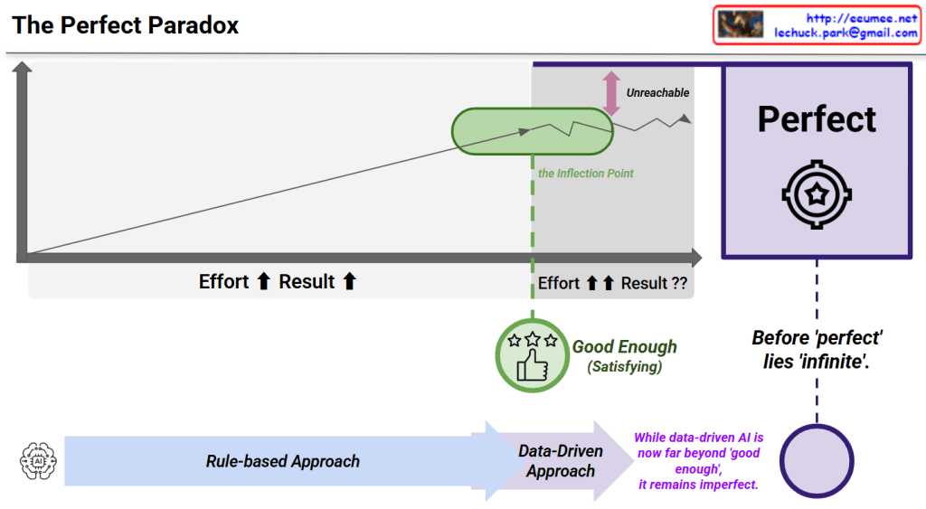
This diagram illustrates “The Perfect Paradox”, explaining the relationship between effort and results. Here are the key concepts:

Graph Analysis

Axes:

  • X-axis: Effort
  • Y-axis: Result

Pattern:

  • Initially, results increase proportionally with effort
  • After the Inflection Point (green circle), dramatically increased effort yields minimal or even diminishing returns
  • “Perfect” exists in an unreachable zone

Core Message

“Good Enough (Satisfying)”

  • Located near the inflection point
  • Represents the optimal effort-to-result ratio

The Central Paradox:

“Before ‘perfect’ lies ‘infinite’.”

This means achieving perfection requires infinite effort.

AI Connection

The bottom arrow shows the evolution of approaches:

  • Rule-based ApproachData-Driven Approach

Key Insight:

“While data-driven AI is now far beyond ‘good enough’, it remains imperfect.”

This suggests that modern AI achieves high performance, but pursuing practical utility is more rational than chasing perfection.


Summary

The Perfect Paradox shows that after a certain inflection point, exponentially more effort produces minimal improvement, making “perfect” practically unreachable. The optimal strategy is achieving “good enough” – the sweet spot where effort and results are balanced. Modern data-driven AI has surpassed “good enough” but remains imperfect, demonstrating that practical excellence trumps impossible perfection.

#PerfectParadox #DiminishingReturns #GoodEnough #EffortVsResults #PracticalExcellence #AILimitations #DataDrivenAI #InflectionPoint #OptimizationStrategy #PerfectionismVsPragmatism #ProductivityInsights #SmartEffort #AIPhilosophy #EfficiencyMatters #RealisticGoals