From ChatGPT with some prompting Certainly, the image represents the process of collecting data from facilities, demonstrating how different technical components interact.
Facility: This indicates the physical equipment or site generating data, likely composed of various sensors and devices.
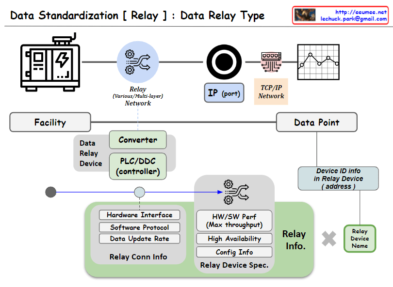
Data Relay Device: It serves as an intermediary, relaying data collected from the facility to the network. It is depicted as being connected to the network via an IP address and port number.
TCP/IP Network: The path through which data is transmitted, utilizing the TCP/IP protocol to transfer data. This network manages the flow of data to the data point.
Data Point: The location where collected data is processed, where important metrics such as software protocol and data collection rate are set.
Network Topology: This represents the physical or logical layout of the network, including performance-related metrics such as the specifications of switches.
TCP/IP Layer: Although not explicitly illustrated in the image, the TCP/IP network is intended to be managed as a distinct logical layer. This emphasizes the advantages of managing and optimizing the data transmission process.
The image visually communicates these technical details, providing an overview of how each component is interconnected for the purpose of data collection and transmission.
From ChatGPT with some prompting The image appears to illustrate the process and key elements involved in data collection from a facility, with a focus on the intermediary step of converting or relaying data through devices such as PLCs (Programmable Logic Controllers) or DDCs (Direct Digital Controllers). These conversion devices play a pivotal role, and their functions are visualized as follows:
Data Conversion (Converter): This converts raw data from the facility into a format that is communicable across a network, ensuring compatibility with other devices through protocol or data format alignment.
Communication Gateway (PLC/DDC controller): The data relay device also serves as a gateway, managing the flow of data between the facility and the TCP/IP network, transmitting data in a form that is understandable to other devices on the network, and sometimes processing complex data.
Relay Information (Relay Info): As depicted, it defines the functional and technical details of the converter, including hardware interfaces, software protocols, data update rates, and relay connection information. This encompasses the device’s performance capabilities (maximum throughput), availability, configuration information, and relay device specifications.
Device Identification Information (Device ID info): Each relay device possesses unique identification information (address), which is a critical parameter for distinguishing and addressing devices within the network.
Relay Device Naming (Relay Device Name): Each device is assigned a discernible name for easy identification and reference within the system.
These components are crucial for standardized communication and processing of data, ensuring efficient collection and prompt handling of data. The diagram is designed to elucidate how these technical elements interact and fulfill their roles in the data relay process.
From Copilot with some prompting The image you shared represents a diagram titled “Facility Data Spec.” Here’s the description:
Image Description:
The diagram depicts the process of defining data requirements centered around facility-based data management.
On the left side, there’s an icon representing a “Facility,” which is connected to elements such as data generation rate, hardware interface, and software protocol.
A relay network (symbolized by gears) is linked to the facility and leads to an IP port.
The IP port connects to a TCP/IP network represented by circuit lines, ultimately leading to a data point.
The data point includes elements like data explanations and data units.
At the top right corner of the image, there are URLs and an email address.
Summary:
The diagram illustrates how data is generated within a facility, transmitted through various networks and protocols, and ultimately represented as data points.
This diagram provides valuable insights for managing facility-related data requirements. Understanding and effectively managing data specifications at the facility level is crucial for efficient data management.
From Gemini with some prompting Facility-centric data definition for facility data management Facility data management is the process of systematically collecting, storing, managing, and analyzing data generated from facilities. Facility data includes information on the facility’s condition, operation, and production. Facility data management can lead to the following benefits:
Improved facility efficiency Prediction and prevention of facility failures Increased productivity Energy savings Facility-centric data definition is a data definition approach that centers on facilities. It offers the following benefits:
Data consistency Improved data accessibility Increased data usability The diagram illustrates the following facility-centric data definition requirements for facility data management:
Facility: The facility is the entity that generates data. Different types of facilities exist, and each type generates different data. Data point: A data point is a unit of data generated from a facility. It includes the data name, data type, and data value. Network: The network is a communication network that connects facilities and data points. Data generated from facilities is transmitted to data points through the network. Data repository: The data repository is a place where data is stored. Different types of data repositories exist, and each type has different characteristics. Data processing: Data processing is the process of analyzing and utilizing data. It includes data cleaning, data analysis, and data visualization. Facility-centric data definition requirements for facility data management:
Data consistency: Facility-centric data definition should ensure data consistency. Data names, data types, and data values should be standardized to maintain data consistency. Data accessibility: Facility-centric data definition should improve data accessibility. The data repository should be appropriately selected, and data access permissions should be managed to enhance data accessibility. Data usability: Facility-centric data definition should increase data usability. Data analysis tools should be utilized, and data-driven decision-making should be implemented to improve data usability. Conclusion:
Facility-centric data definition requirements should be considered for facility data management. Facility-centric data definition can enhance data consistency, accessibility, and usability, leading to improved facility efficiency, productivity, and energy efficiency.
From DALL-E with some prompting This image visually represents “3 Key Strategies for DC Operation.”
Transform
Digitalization: Transitioning data centers to digital technology.
KPI (Key Performance Indicators)
PUE (Power Usage Effectiveness) & Monitoring
Automation
Data API Service
Use
Data Platform: Establishing platforms for data management and utilization.
Standardization
Platform
Continuous Upgrade
New!!
Verify
AI: Validating efficiency and performance of data centers through AI.
Real AI
Early Warning
Energy Operation
These three strategies are interconnected with three objectives: “Experience to Digital,” “Continuous Innovation,” and “AI DC Now!!” This illustrates that the operation of data centers is moving towards impacting humans through digitalization, innovation, and the application of AI technology, driving transformation across the industry.
From DALL-E with some prompting The image presents different data collection configurations in facility management systems:
Direct Connection: Equipment directly sends data to the network without any intermediate device.
Controller: Data is collected via a PLC (Programmable Logic Controller), DDC (Direct Digital Control), or Gateway from the equipment and then sent to the network.
Dedicated Meter: Specialized meters are used to collect specific data, which is then transferred directly to the network.
Dedicated Meter & Controller: A setup where dedicated meters work in conjunction with a PLC/DDC/Gateway for data collection and subsequent control before networking.
Internal Control System: An integrated control system manages and monitors data internally before it connects to the network.
Solution System: a Standalone system that is self-contained with full functionalities for a specific operation.
This depiction emphasizes the progression from direct data routing to more complex systems involving multiple stages of data handling and integration.
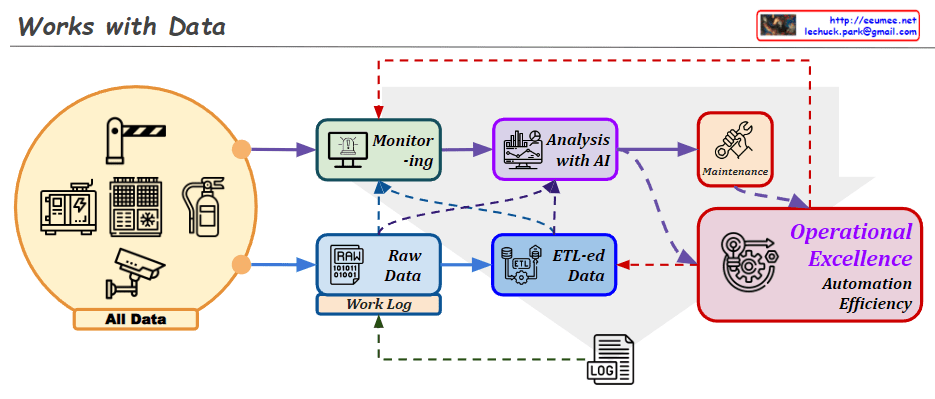
From DALL-E with some prompting The image describes a data workflow process that involves various stages of data handling and utilization for operational excellence. “All Data” from diverse sources feeds into a monitoring system, which then processes raw data, including work logs. This raw data undergoes ETL (Extract, Transform, Load) procedures to become structured “ETL-ed Data.” Following ETL, the data is analyzed with AI to extract insights and inform decisions, which can lead to actions such as maintenance. The ultimate goal of this process is to achieve operational excellence, automation, and efficiency.
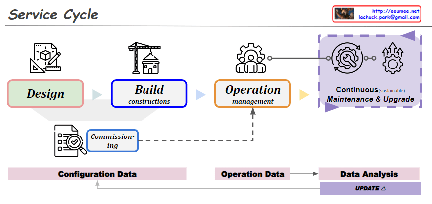
From DALL-E with some prompting The image depicts a “Service Cycle” comprising several phases in a service’s lifecycle. These phases are visually represented and include “Design,” “Build constructions,” and “Operation management.” Additionally, the cycle includes “Commissioning” and “Continuous (sustainable) Maintenance & Upgrade” stages, emphasizing the ongoing process of maintaining and upgrading services. The flow of information through “Configuration Data,” “Operation Data,” and “Data Analysis” is also presented, highlighting the importance of data in managing and improving service operations.