OSPF & BGP

from DALL-E with some prompting
The image is an illustrative diagram explaining the interaction between two key protocols used in networking: OSPF (Open Shortest Path First) and BGP (Border Gateway Protocol).

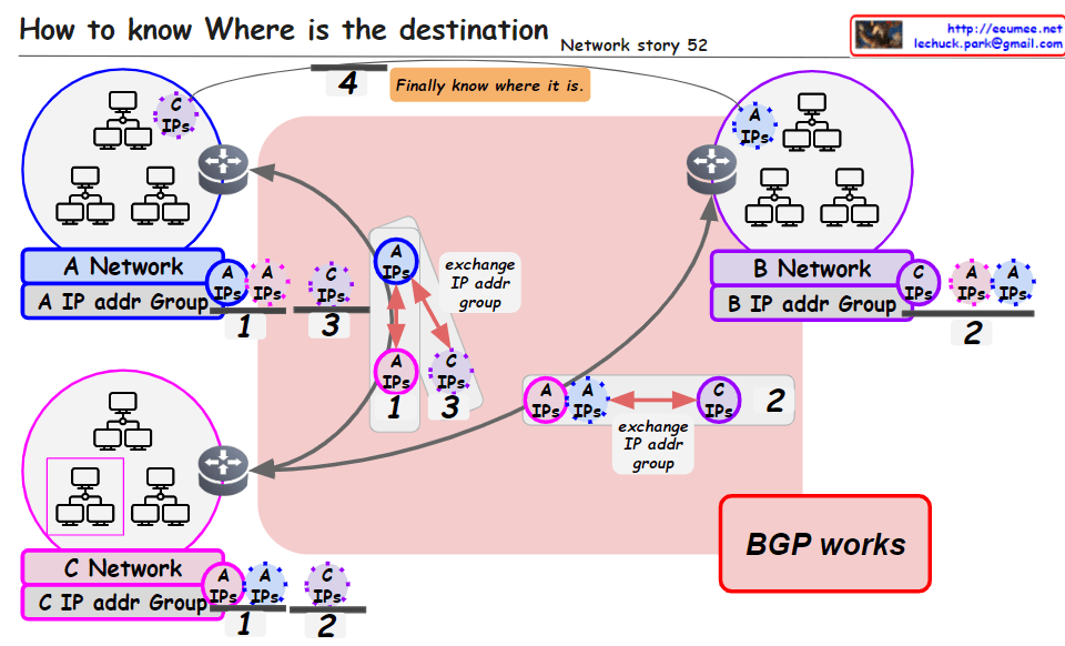
  • In the center, we have a network labeled “AS (Autonomous System)” which is a collection of connected IP routing prefixes under the control of one or more network operators that presents a common, clearly defined routing policy to the internet.
  • Within the AS, the diagram shows a smaller network with purple lines connecting different nodes (routers), representing the OSPF protocol. OSPF is an interior gateway protocol used within an AS that distributes routing information between routers belonging to a single Autonomous System. The key features listed are:
    • “Sharing Link State (broadcast)” which means OSPF routers send link state advertisements to share the state of each directly connected link.
    • “with a Bandwidth” indicates that OSPF takes bandwidth into account when calculating the best route.
    • “Find Short Path (Dijkstra)” refers to OSPF using Dijkstra’s algorithm to find the shortest path through the network based on the cumulative cost of reaching each node.
  • On the right side of the diagram, there’s a larger network outlined in red, with blue lines connecting to a central node. This represents the BGP protocol, which is used between different ASes, especially at the borders. The features listed for BGP are:
    • “Border (of the AS) Gateway” which is the point where an AS connects to another AS.
    • “Sharing Routing Table between Border Gateways” means that BGP is responsible for exchanging routing information between autonomous systems, allowing them to see each other’s networks and determine the best paths.

The diagram uses solid lines to denote direct connections and dashed lines for indirect connections. The interplay between OSPF and BGP is critical for the overall functioning of the internet, with OSPF managing routes within an AS and BGP managing routes between ASes.

Anomaly Traffic Detection#1

From DALL-E with some prompting
The flowchart illustrates a four-step network anomaly detection process:

  1. Data Collection: Gather various types of network data.
  2. Protocol Usage: Employ SNMP, SFLOW/NETFLOW, and other methods to extract the data.
  3. Analysis: Analyze Ethernet and TCP/IP header data for irregularities.
  4. Control: Implement countermeasures like blocking traffic or controlling specific IP addresses.

The expected benefits of this process include enhanced network security through early detection of anomalies, the ability to prevent potential breaches by blocking suspicious traffic, and improved network management via real-time analysis and control.

Resource limitation of processes

From DALL-E with some prompting

This image represents a concept diagram for ‘Control Groups’ (Cgroups) used in the Linux operating system. Cgroups provide the capability to manage and limit system resource usage for groups of processes. Each control group can have limits set for various resources such as CPU, memory, block I/O, and network bandwidth.

Groups A, B, C: Each circle represents a separate control group, and the gear icons within each group symbolize the processes assigned to that group.

The central graphical elements represent various system resources:

CPU: Represents CPU time and usage (milliseconds, percentage).
Memory (RAM): Shows total memory usage, memory usage ratio, and memory usage limit.
Block I/O: Illustrates disk read/write speed, number of input/output operations per second (IOPS), and latency.
Network Bandwidth: Displays transmission speed and bandwidth usage ratio.
In the upper right, there’s a section with the text “Resource limits per group” alongside icons for each resource and a question-marked group. This likely illustrates the resource limitations that can be set for each control group.

At the bottom, “Linux 2.6.24 +” indicates that the Cgroups feature is available from Linux kernel version 2.6.24 onwards.

Overall, the image seems to have been created to explain the concept of Cgroups and how resources can be managed for different groups within a system.


Anomaly Connection Detection #0

from DALL-E with some prompting
The image seems to illustrate the concept of anomaly detection in network security. A user is shown with a green line leading to a server, indicating normal interaction, while a red line leading from a network criminal suggests malicious activity. The network architecture is in place to mirror and tap into the data traffic, allowing for the steering of packets for closer inspection. An alert (!!) signifies the detection of an anomaly. Below, details of what is monitored are given: raw or sampled packets, TCP/IP 5-tuples, geographic IP locations, bandwidth, and new detection areas including DNS and HTTP header information. This represents a multifaceted approach to identifying and responding to potential security threats within a network.

Where it is?

From Bard with some prompting

1. The sender sends a packet using the destination IP address.

2. Routers use the destination IP address to determine the path to forward the packet.

3. Routers use the BGP protocol to share routing information with other routers.

4. The packet travels through multiple routers until it reaches the destination network.

5. The router in the destination network uses the destination IP address to forward the packet to the destination host.

6. The destination host receives and processes the packet.

Note:

  • This summary only explains the basic concepts, and the actual network environment can be more complex.
  • For more information, please refer to networking books or websites.


Network Monitoring with AI

from DALL-E with some prompting
The image portrays a network monitoring system enhanced by AI, specifically utilizing deep learning. It shows a flow from the network infrastructure to the identification of an event, characterized by computed data with time information and severity. The “One Event” is clearly defined to avoid ambiguity. The system identifies patterns such as the time gap between events, event count, and relationships among devices and events, which are crucial for a comprehensive network analysis. AI deep learning algorithms work to process additional data (add-on data) and ambient data to detect anomalies and support predictive maintenance within the network.

Switching & Routing (Origin)

From DALL-E with some prompting
The image delineates the foundational aspects of network switching and routing based on their origins. Switching, historically in LANs, involved the broadcasting of packets, which modern switches now intelligently direct or block based on MAC addresses and VLAN information. Routing originally functioned to determine packet pathways over networks using IP address information. While these were once discrete tasks performed by separate devices, contemporary network technology often integrates both functions within the same hardware, allowing switches to perform some routing tasks and vice versa, reflecting the evolution and convergence of networking equipment.