AI Prediction

From Claude with some prompting
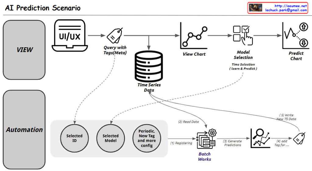
This diagram illustrates an AI Prediction System workflow, which is divided into two main sections:

  1. Upper Section (VIEW):
  • Starts with a UI/UX interface
  • Executes queries with tags (metadata)
  • Connects to time series data storage
  • Displays data visualization charts
  • Includes model selection step
  • Finally generates prediction charts
  1. Lower Section (Automation):
  • Selected ID
  • Selected Model
  • Periodic, new tags and additional configuration
  • Batch work processing (consisting of 4 steps):
    1. Registering
    2. Read Data
    3. Generate Predictions
    4. Add Tag
  • Writing new time series data

The system provides two main functionalities:

  1. A user interface for direct data viewing and prediction execution
  2. Automated batch processing for periodic predictions and data updates

Key Components:

  • Time Series Data storage as a central database
  • View Chart for data visualization
  • Model Selection with time selection (learn & predict)
  • Predict Chart as the final output
  • Batch Works system for automated processing

The workflow demonstrates a comprehensive approach to handling both manual and automated AI predictions, combining user interaction with systematic data processing and analysis. The system appears designed to handle time series data efficiently while providing both immediate and scheduled prediction capabilities.

Synchronization Issues

From Claude with some prompting
This diagram illustrates various synchronization issues and their solutions in system synchronization processes. Let me break it down into three main parts:

  1. Copy-related Issues
  • Problems: High Load and Lack of Real Time
  • Solutions:
    • Increment Copy
    • Sync Scheduling
  1. Replication-related Issues
  • Problem: Network Delay
  • Solutions:
    • Timestamp Control
    • Checksum for comparison
  1. Synchronization-related Issues
  • Problems: Deadlock and Race Condition
  • Solutions:
    • Timeout settings
    • Priority Control
    • Semaphore/Mutex
    • Failure Recovery

Key Processes:

  • Maintaining “Keep the Same” status between systems
  • Detecting and notifying all changes (Noti & Detect All Changes)
  • Reflecting changes to other systems (reflect)

The diagram is well-structured with these notable features:

  1. Hierarchical Organization
  • Shows synchronization issues from top to bottom level
  • Progresses from Copy → Replications → Synchronization → Process Synchronization
  1. Clear Problem-Solution Mapping
  • Problems presented on the left (High Load, Network Delay, Deadlock, etc.)
  • Solutions presented on the right (visualized as green buttons)
  1. Visual Consistency
  • Problems shown in orange boxes
  • Solutions shown in green buttons
  • Process flows clearly indicated with arrows
  1. Practical Approach
  • Includes both theoretical concepts and practical implementation elements
  • Incorporates operational considerations like Failure Recovery

This structured organization serves as a valuable guide for understanding and solving complex synchronization problems in distributed systems or database replication systems.

MPLS

From Claude with some prompting
Let me explain this MPLS (Multiprotocol Label Switching) diagram:

  1. Left Section – Network Stack:
  • Application layer
  • TCP/UDP layer
  • IP layer
  • Ethernet layer
  1. Middle Section – MPLS Label Structure:
  • Label (20 bits): Used for routing
  • Experimental (3 bits): For QoS (Quality of Service) priority
  • Bottom of Stack (1 bit): Indicates if it’s the last label (Not Bottom: 0)
  • TTL (8 bits): Time to Live, prevents looping
  1. Right Section – MPLS Network Operation:
  • Label Edge Router (LER): Adds/removes labels at network boundaries
  • Label Switching Router (LSR): Performs label-based switching
  • Packets expire when TTL reaches 0
  • Routing based on priority using Experimental (QoS) bits

Operational Flow:

  1. Add Label Header: When packets enter MPLS network
  2. Routing by Label: Packet forwarding based on labels with Priority by Exp(QoS)
  3. Remove Label Header: When packets exit MPLS network

Key Benefits of MPLS:

  • Fast packet forwarding (label-based switching)
  • QoS support
  • Efficient traffic engineering
  • Support for multiple network protocols

The diagram shows how MPLS creates a more efficient and manageable network by using label-based forwarding instead of traditional IP routing. Labels can be stacked (Label Stack-able) for more complex routing scenarios, and the TTL field helps prevent infinite routing loops.

CDC & ETL

From Claude with some prompting
Here’s the interpretation of the image explaining CDC (Change Data Capture) and ETL (Extract, Transform, Load) processes. The diagram is divided into three main sections:

  1. Top Section:
  • Shows CDC/ETL process from “For Operating” database to “For Analysis” database.
  1. Middle Section (CDC):
  • Illustrates the Change Data Capture process
  • Shows how changes C1 through C5 are detected and captured
  • Key features:
    • Realtime processing
    • Sync Duplication
    • Efficiency
  1. Bottom Section (ETL):
  • Demonstrates traditional ETL process:
    • Extract
    • Transform
    • Load
  • Processing characteristics:
    • Batch process
    • Data Transform
    • Data Integrate

The diagram contrasts two main approaches to data integration:

  1. CDC: Real-time approach that detects and synchronizes changes as they occur
  2. ETL: Traditional batch approach that extracts, transforms, and loads data

This visualization effectively shows how CDC provides real-time data synchronization while ETL handles data in batches, each serving different use cases in data integration strategies.