Network 1

From Claude with some prompting
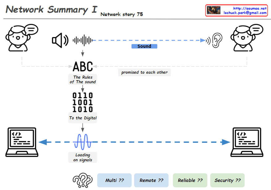
This image, titled “Network Summary I”, illustrates the basic process of network communication in several steps:

  1. Sound Transmission: It shows sound being transmitted between two people.
  2. Communication Rules: The phrase “ABC – The Rules of The sound” indicates that there are agreed-upon rules for sound transmission.
  3. Digital Conversion: It demonstrates how sound is converted into digital signals, represented as “0110 1001 1010”.
  4. Signal Transmission: The phrase “Loading on signals” along with a waveform shows how signals are transmitted between two computers.
  5. Network Challenges: At the bottom, the questions “Multi ??”, “Remote ??”, “Reliable ??”, and “Security ??” present key issues to be addressed after establishing a network connection.

This diagram provides a basic overview of how voice communication is converted to digital data and transmitted over computer networks. It then poses questions about how to handle multiplexity, remote connections, reliability, and security in actual network implementations.

By presenting these challenges, the image implies the necessity for more complex networking protocols like TCP/IP and various networking equipment. It effectively summarizes the journey from basic principles of network communication to the complex issues faced in real-world network implementation, serving as an educational tool to introduce networking concepts.

HTTP Changes

From Claude with some prompting
HTTP: HTTP uses text-based HTML with a head and body structure. HTTP/1.1 introduced Keep-Alive for maintaining TCP connections, but suffers from header overhead and Head-of-Line Blocking issues. Servers cannot push data without a client request.

HTTP/2: HTTP/2 introduced binary framing to improve performance. It enhances efficiency through header compression and multiplexing, and added server push functionality. It also strengthened authentication and encryption using TLS/SSL.

HTTP/3: HTTP/3 operates over the QUIC protocol using UDP instead of TCP. It includes TLS 1.3 by default and provides lower latency and improved multiplexing. HTTP/3 significantly enhances performance through 0-RTT connection establishment, elimination of TCP handshakes, and solving Head-of-Line Blocking issues. It also offers reliable data streams over UDP and ensures data ordering on each stream.

HTTP Service components

From Claude with some prompting
This image illustrates the network structure of an HTTP service. The main components are:

Client Side:

  • Browser: Handles URL requests, HTML parsing, and JavaScript execution
  • OS: Runs the browser, translates URL (domain) to IP

Internet:

  • DNS: Converts domain names to IP addresses
  • IP: Transfers data using IP addresses

Server Side:

  • OS (Operating System): Runs applications, manages IP network
  • TLS: Handles encryption
  • WEB:
    • Manages HTML embedding
    • Handles JSP (JavaServer Pages)
    • Typically deals with static content and some dynamic content generation
  • WAS (Web Application Server):
    • Handles server-side programming and application logic
    • Manages complex dynamic content generation
    • Interacts with the database
    • Handles business logic of the application
  • DB: Database for storing and retrieving data for web services

The diagram shows the entire process of how an HTTP request is handled, from the web browser to the server’s database. It briefly explains the technologies and protocols involved at each step, providing a helpful overview of the basic structure of web services.

RDMA : Remote Direct Memory Access

From Claude with some prompting
This image explains RDMA (Remote Direct Memory Access). Here’s an interpretation in English:

  1. The top of the image shows that RDMA allows one system to access the memory of another system without overheads.
  2. The bottom left box lists the main advantages of RDMA:
    • CPU Load down
    • High Bandwidth
    • Low Latency
    • Scale-out
  3. The central box describes key features of RDMA:
    • Zero-Copy
    • Direct Memory Access
    • Memory-Mapped I/O
    • Scatter-Gather I/O
  4. The bottom right box lists RDMA-related components:
    • RDMA Device
    • RDMA Protocol
    • RDMA Memory Window (defined as “a memory region accessible via RDMA”)

The image provides a concise overview of RDMA technology, highlighting its main features and benefits. It illustrates how RDMA enables efficient, direct memory access between systems, reducing CPU load and improving performance in terms of bandwidth and latency.

nagle for TCP

From Claude with some prompting
This image illustrates the TCP (Transmission Control Protocol) packet structure and the Nagle algorithm.

  1. Top section:
    • Shows data transfer between two computers.
    • Demonstrates how data (payload) is divided into multiple packets for transmission.
  2. Middle section – Packet structure:
    • Data Payload: The actual data being transmitted
    • TCP/IP header: Contains control information for communication
    • Ethernet header: 14 Bytes
    • IPv4 header: 20 Bytes
    • TCP header: 20 Bytes
    • Data + Padding: Actual data and padding added if necessary
    • MTU Limit: Maximum Transmission Unit limit
  3. Bottom section – Nagle’s Algorithm:
    • Normal TCP/IP transmission: Small data packets are sent individually
    • With Nagle’s Algorithm: Small data packets are combined into larger packets before transmission
    • Packet sending conditions:
      1. When an ACK is received
      2. On timeout
      3. When the TCP sending window overflows

The image effectively demonstrates the packet structure in TCP communications and explains how the Nagle algorithm improves network efficiency. The main purpose of Nagle’s algorithm is to reduce network overhead by bundling small packets together before transmission.

DNS Caching SEQ

From Claude with some prompting
This improved diagram illustrates the DNS caching sequence more comprehensively. Here’s a breakdown of the process:

  1. A user types a URL in a browser.
  2. The system attempts to translate the domain to an IP address using DNS caches.
  3. Process Keep it: Checks the process-level DNS cache. If the information isn’t found here (“No”), it moves to the next step.
  4. OS Keep it: Checks the operating system-level DNS cache. For Linux, it uses the “nslookup -c domain” command, while for Windows, it uses “ipconfig /displaydns”. If the information isn’t found here (“No”), it proceeds to the next step.
  5. Query to the Resolver Server: The system queries the DNS resolver server. The resolver’s information is found in “/etc/resolv.conf” for Linux or the Windows Registry for Windows systems.
  6. If the resolver doesn’t have the information cached (“No”), it initiates a recursive query through the DNS hierarchy:
    • Root DNS
    • TLD (Top-Level Domain) server
    • Authoritative server
  7. Once the IP address is obtained, an HTTP request is sent to the web server.

This diagram effectively shows the hierarchical nature of DNS resolution and the fallback mechanisms at each level. It demonstrates how the system progressively moves from local caches to broader, more authoritative sources when resolving domain names to IP addresses. The addition of the DNS hierarchy (Root, TLD, Authoritative) provides a more complete picture of the entire resolution process when local caches and the initial resolver query don’t yield results.

DNS work sequence

From Claude with some prompting
This image illustrates the DNS (Domain Name System) work sequence. Here’s a breakdown:

  1. It starts with typing a URL in a browser. For example, entering “abc.com” requires translation to an IP address.
  2. The DNS resolution process begins, involving multiple levels of DNS resolvers with caching capabilities.
  3. At each level, there’s a “Have I already? (caching?)” check. If the information is cached, it’s used immediately.
  4. If not found, it proceeds to the next level:
    • Root DNS: Provides information on top-level DNS servers (Managed by IANA)
    • TLD (Top-Level Domain): Gives information on domains like “.com” (Managed by various organizations under ICANN)
    • Authoritative Server: Provides actual domain information (e.g., abc.com, managed by hosting providers or domain owners)
  5. Through these stages, the system finds the necessary information to ultimately obtain the IP address of the entered domain.

This diagram effectively demonstrates the hierarchical structure of DNS lookup process and the caching mechanism at each stage.