IP & Domain address

From DALL-E with some prompting
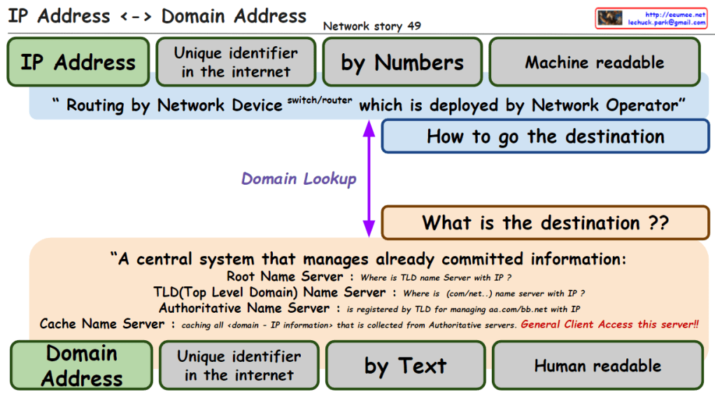
The image explains the relationship between IP addresses and domain addresses within the context of the internet and network infrastructure. Here’s a breakdown of the components:

  1. IP Address: Identified as a unique identifier in the internet by numbers, which is machine-readable. It is used for routing by network devices like switches and routers, deployed by network operators.
  2. Domain Lookup: The process that determines how to get the destination, asking “what is the destination?”
  3. Domain Address: Also a unique identifier on the internet, represented by text, which is human-readable.
  4. Central System of Name Servers:
    • Root Name Server: Answers queries about the location of the Top-Level Domain (TLD) name server associated with an IP.
    • TLD Name Server: Provides information about the domain’s name server associated with certain domain extensions like .com or .net.
    • Authoritative Name Server: Holds the definitive records for domains within its TLD.
    • Cache Name Server: Caches all domain-to-IP information collected from authoritative servers, accessible to general clients.

The overall message emphasizes the conversion between IP addresses (numeric form) and domain addresses (text form), which is crucial for navigating the internet and finding the correct destination for data packets. It also highlights the significance of the Domain Name System (DNS) in translating between human-readable domain names and machine-readable IP addresses.

Overall IP Network

From DALL-E with some prompting
The image is a diagram explaining the overall structure and data flow of an IP network.

Overall IP network: The entire structure of an IP network
Ethernet In the LAN: Ethernet used within the Local Area Network (LAN)
Identification in the internet: Identifying devices on the internet
OSPF short path with IP addresses: Open Shortest Path First (OSPF) routing protocol finds the shortest path using IP addresses
Addressing/Routing to the peer: Assigning addresses and routing to peer devices
BGP to get/share IP (other & me): Border Gateway Protocol (BGP) is used for obtaining and sharing IP addresses between others and oneself
Service Connection: Establishing a service connection
IP address ↔ Domain address: The relationship between IP addresses and domain addresses
DNS Easy to keep an internet address by Domain name: Domain Name System (DNS) makes it easy to maintain an internet address by using domain names
On TCP/UDP: Operating on TCP (Transmission Control Protocol) and UDP (User Datagram Protocol)
The diagram illustrates how data moves within a network. For instance, when a user accesses web services using the HTTP protocol, the DNS translates domain names into IP addresses, and then a service connection is established using the IP address over TCP/UDP protocols. Routing protocols such as OSPF and BGP are used to find the optimal path for data transmission through internal networks and the wider internet, respectively.


ARP/RARP

From DALL-E with some prompting
The image focuses on the primary uses and applications of ARP and RARP protocols in a network. ARP (Address Resolution Protocol) is utilized to translate IP addresses into MAC addresses to ensure packets are delivered to the correct destination. This information is stored in the ARP table, facilitating packet forwarding across the Ethernet network. On the other hand, RARP (Reverse Address Resolution Protocol) has largely been superseded by DHCP (Dynamic Host Configuration Protocol). DHCP is commonly used to dynamically assign IP addresses to devices on a network and to automatically configure network setting information.

Traceroute works 2

From DALL-E with some prompting
The image provides a detailed explanation of the ‘traceroute’ network diagnostic tool and how it functions, along with potential error messages and their meanings. The ‘traceroute’ command can work with not only ICMP but also TCP/UDP protocols, allowing it to trace the path data packets take through a network to reach the destination. Specifically, the command ‘traceroute -T -p 80 [destination]’ is used to trace the route to the destination over TCP port 80.

The diagram displays several routers (labeled 1, 2, 3, 4) that the traceroute may encounter on its path. Accompanying these are four cases, each illustrating a different error scenario that might occur during the trace:

  • Case1: A TCP block might occur, potentially due to a firewall or Access Control List (ACL), indicated by ICMP Type 3, Code 2 (Protocol Unreachable) or Code 10 (Communication with Destination Host is Administratively Prohibited).
  • Case2: A block on TCP Port 80 might be encountered, also possibly because of a firewall or ACL.
  • Case3: A general TCP block, which might be caused by iptables or similar tools, indicated by ICMP Type 3, Code 2 (Protocol Unreachable) or Code 13 (Communication Administratively Prohibited).
  • Case4: A block on TCP Port 80 or a service not being open on the destination, which can result in messages such as “Port Unreachable” or “Connection Refused”.

Each case provides the relevant ICMP message type and code that might be returned if such a situation occurs, which is crucial for network administrators or IT professionals in diagnosing and resolving network connectivity issues.

Traceroute works I

From The Bard with some prompting
The image is a diagram of how a traceroute works. Traceroute is a tool that uses ICMP packets to determine the path that a packet takes from a source to a destination.

The image shows the following steps:

The source sends an ICMP packet with a TTL (time to live) of 1.
The first router that receives the packet decrements the TTL by 1 and sends it to the next router.
If the TTL reaches 0 before reaching the destination, the router sends an ICMP packet back to the source with an error message.
The source then sends an ICMP packet with a TTL of 2.
The process repeats until the destination is reached.
The text in the image provides additional information about each step. For example, the text for step 1 states that the source sends an ICMP packet with a TTL of 1. This means that the packet will be discarded by any router that receives it after it has traveled 1 hop.

The image also shows the following information:

  • The source IP address is 192.168.1.1.
  • The destination IP address is 203.0.113.5.
  • The RTT (round-trip time) for each hop is shown in milliseconds.

The image is a useful tool for understanding how traceroute works. It can be used to troubleshoot network problems by identifying the routers that are causing delays or errors.

Here is a more concise summary of the image:

Traceroute uses ICMP packets to determine the path that a packet takes from a source to a destination. The source sends an ICMP packet with a TTL of 1. If the TTL reaches 0 before reaching the destination, the router sends an ICMP packet back to the source with an error message. The source then sends an ICMP packet with a TTL of 2. The process repeats until the destination is reached.tunesharemore_vertadd_photo_alternate

PING with “Don’t Fragment”

From DALL-E with some prompting
The image outlines a networking concept involving the transmission of ICMP (Internet Control Message Protocol) packets with the “Don’t Fragment” flag set, which is part of the IP (Internet Protocol) flags. Here’s a breakdown of the key elements in the image:

  1. Header Section:
    • Type of Service: Indicates the quality of service for the packet.
    • IP Flags: Contains the “Don’t Fragment” (DF) flag, indicated by setting the D bit to 0. The “MF” bit represents whether the packet is the last fragment.
    • Type: For an ICMP Echo Request, this value is set to 8.
    • Code: Used to further specify the message.
  2. Packet Transmission:
    • The command ping -f is used to send a ping with the DF flag set, which means the packets should not be fragmented, even if their size exceeds the MTU (Maximum Transmission Unit) of the network path.
    • Case #1: If the packet size is less than the MTU, the packet is forwarded without issue.
    • Case #2: If the packet size is greater than the MTU, it needs to be fragmented. However, because the DF flag is set, it can’t be fragmented, resulting in a “Destination Unreachable” message with code 3 (Fragmentation needed and DF set).
  3. Error Handling:
    • The ICMP error message “Destination Unreachable” with a code of “3” is returned if a packet with the DF flag set needs to be fragmented to continue along the network path but cannot be due to the flag.

This image is a guide to understanding how the “Don’t Fragment” flag in IP packets affects their transmission over networks and how ICMP is used for error reporting when the flag is set.

TTL(time to live) in ip packets

From DALL-E with some prompting
The image provides an educational visualization of how the “Time to Live” (TTL) value in the Internet Protocol (IP) is used to manage the life span of data packets during transmission. TTL is a crucial part of the IP header, which is decremented by each router the packet passes through. When the TTL value reaches zero, the packet is discarded, preventing it from circulating indefinitely.

The diagram outlines the following key points:

  1. ICMP Packets: It shows the process of sending ICMP (Internet Control Message Protocol) packets, specifically an Echo Request, which is a common method for pinging a destination IP address to test connectivity.
  2. TTL Decrement: Each hop in the network decreases the TTL value of the packet by one. This decrement process helps determine how many network hops the packet has passed through to reach its destination.
  3. TTL in Action: The sequence of routers illustrates the TTL value decreasing from 64 down to 57 as the packet travels across seven network hops.
  4. Command Usage: It includes a command line example # ping -t [ttl] (Dest ip address) that specifies how to ping with a defined TTL value.
  5. TTL Analysis: It suggests that analyzing TTL values can help detect anomalies in packets, changes of routes from the same peer IP address, among other uses. For example, receiving a packet with an unusually high TTL value like 500 could indicate an abnormality.
  6. Receiving and Responding: The final part of the image shows a receiving computer that gets the ICMP packet with a TTL of 57 and replies with an Echo Response.

This visual aid is likely used for educational purposes to teach about network packet management, routing, and network troubleshooting techniques.