From DALL-E with some prompting The image focuses on the primary uses and applications of ARP and RARP protocols in a network. ARP (Address Resolution Protocol) is utilized to translate IP addresses into MAC addresses to ensure packets are delivered to the correct destination. This information is stored in the ARP table, facilitating packet forwarding across the Ethernet network. On the other hand, RARP (Reverse Address Resolution Protocol) has largely been superseded by DHCP (Dynamic Host Configuration Protocol). DHCP is commonly used to dynamically assign IP addresses to devices on a network and to automatically configure network setting information.
From DALL-E with some prompting The image provides a detailed explanation of the ‘traceroute’ network diagnostic tool and how it functions, along with potential error messages and their meanings. The ‘traceroute’ command can work with not only ICMP but also TCP/UDP protocols, allowing it to trace the path data packets take through a network to reach the destination. Specifically, the command ‘traceroute -T -p 80 [destination]’ is used to trace the route to the destination over TCP port 80.
The diagram displays several routers (labeled 1, 2, 3, 4) that the traceroute may encounter on its path. Accompanying these are four cases, each illustrating a different error scenario that might occur during the trace:
Case1: A TCP block might occur, potentially due to a firewall or Access Control List (ACL), indicated by ICMP Type 3, Code 2 (Protocol Unreachable) or Code 10 (Communication with Destination Host is Administratively Prohibited).
Case2: A block on TCP Port 80 might be encountered, also possibly because of a firewall or ACL.
Case3: A general TCP block, which might be caused by iptables or similar tools, indicated by ICMP Type 3, Code 2 (Protocol Unreachable) or Code 13 (Communication Administratively Prohibited).
Case4: A block on TCP Port 80 or a service not being open on the destination, which can result in messages such as “Port Unreachable” or “Connection Refused”.
Each case provides the relevant ICMP message type and code that might be returned if such a situation occurs, which is crucial for network administrators or IT professionals in diagnosing and resolving network connectivity issues.
From The Bard with some prompting The image is a diagram of how a traceroute works. Traceroute is a tool that uses ICMP packets to determine the path that a packet takes from a source to a destination.
The image shows the following steps:
The source sends an ICMP packet with a TTL (time to live) of 1. The first router that receives the packet decrements the TTL by 1 and sends it to the next router. If the TTL reaches 0 before reaching the destination, the router sends an ICMP packet back to the source with an error message. The source then sends an ICMP packet with a TTL of 2. The process repeats until the destination is reached. The text in the image provides additional information about each step. For example, the text for step 1 states that the source sends an ICMP packet with a TTL of 1. This means that the packet will be discarded by any router that receives it after it has traveled 1 hop.
The image also shows the following information:
The source IP address is 192.168.1.1.
The destination IP address is 203.0.113.5.
The RTT (round-trip time) for each hop is shown in milliseconds.
The image is a useful tool for understanding how traceroute works. It can be used to troubleshoot network problems by identifying the routers that are causing delays or errors.
Here is a more concise summary of the image:
Traceroute uses ICMP packets to determine the path that a packet takes from a source to a destination. The source sends an ICMP packet with a TTL of 1. If the TTL reaches 0 before reaching the destination, the router sends an ICMP packet back to the source with an error message. The source then sends an ICMP packet with a TTL of 2. The process repeats until the destination is reached.tunesharemore_vertadd_photo_alternate
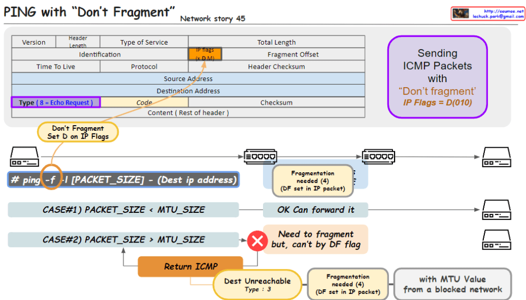
From DALL-E with some prompting The image outlines a networking concept involving the transmission of ICMP (Internet Control Message Protocol) packets with the “Don’t Fragment” flag set, which is part of the IP (Internet Protocol) flags. Here’s a breakdown of the key elements in the image:
Header Section:
Type of Service: Indicates the quality of service for the packet.
IP Flags: Contains the “Don’t Fragment” (DF) flag, indicated by setting the D bit to 0. The “MF” bit represents whether the packet is the last fragment.
Type: For an ICMP Echo Request, this value is set to 8.
Code: Used to further specify the message.
Packet Transmission:
The command ping -f is used to send a ping with the DF flag set, which means the packets should not be fragmented, even if their size exceeds the MTU (Maximum Transmission Unit) of the network path.
Case #1: If the packet size is less than the MTU, the packet is forwarded without issue.
Case #2: If the packet size is greater than the MTU, it needs to be fragmented. However, because the DF flag is set, it can’t be fragmented, resulting in a “Destination Unreachable” message with code 3 (Fragmentation needed and DF set).
Error Handling:
The ICMP error message “Destination Unreachable” with a code of “3” is returned if a packet with the DF flag set needs to be fragmented to continue along the network path but cannot be due to the flag.
This image is a guide to understanding how the “Don’t Fragment” flag in IP packets affects their transmission over networks and how ICMP is used for error reporting when the flag is set.
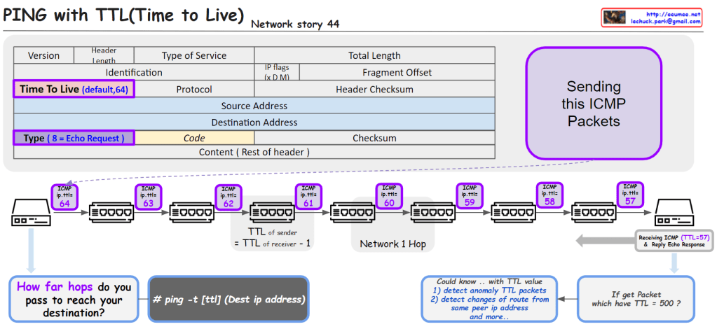
From DALL-E with some prompting The image provides an educational visualization of how the “Time to Live” (TTL) value in the Internet Protocol (IP) is used to manage the life span of data packets during transmission. TTL is a crucial part of the IP header, which is decremented by each router the packet passes through. When the TTL value reaches zero, the packet is discarded, preventing it from circulating indefinitely.
The diagram outlines the following key points:
ICMP Packets: It shows the process of sending ICMP (Internet Control Message Protocol) packets, specifically an Echo Request, which is a common method for pinging a destination IP address to test connectivity.
TTL Decrement: Each hop in the network decreases the TTL value of the packet by one. This decrement process helps determine how many network hops the packet has passed through to reach its destination.
TTL in Action: The sequence of routers illustrates the TTL value decreasing from 64 down to 57 as the packet travels across seven network hops.
Command Usage: It includes a command line example # ping -t [ttl] (Dest ip address) that specifies how to ping with a defined TTL value.
TTL Analysis: It suggests that analyzing TTL values can help detect anomalies in packets, changes of routes from the same peer IP address, among other uses. For example, receiving a packet with an unusually high TTL value like 500 could indicate an abnormality.
Receiving and Responding: The final part of the image shows a receiving computer that gets the ICMP packet with a TTL of 57 and replies with an Echo Response.
This visual aid is likely used for educational purposes to teach about network packet management, routing, and network troubleshooting techniques.
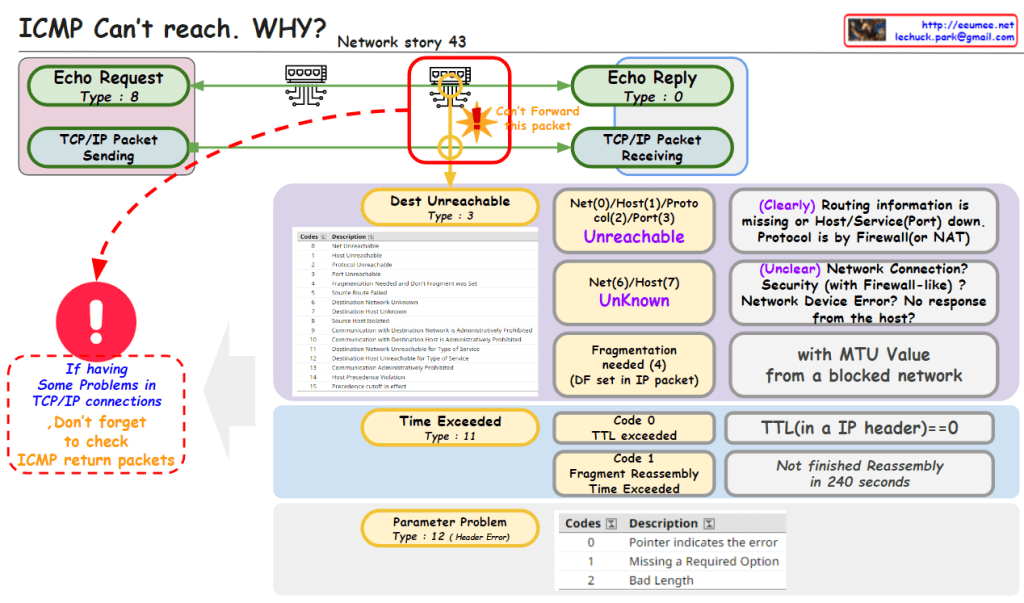
From DALL-E with some prompting The image is an educational diagram explaining different ICMP (Internet Control Message Protocol) messages that indicate problems in TCP/IP network connections. When an “Echo Request” is sent and the network is unable to forward the packet, the ICMP may return various error messages:
“Destination Unreachable” (Type 3) can mean that the network/host/protocol/port is unreachable. The reasons can be varied, such as the route is missing, the host or service on the port is down, or the protocol is blocked by a firewall or NAT (Network Address Translation).
“Time Exceeded” (Type 11) indicates that the time-to-live (TTL) of a packet has reached zero, meaning the packet has taken too long to reach its destination, or fragment reassembly time was exceeded.
“Parameter Problem” (Type 12) points to issues like header errors where certain required information is missing or incorrect.
The diagram also emphasizes the importance of checking ICMP return packets for troubleshooting network issues. It provides a detailed list of ICMP types and codes along with their descriptions to assist in identifying the specific nature of the network problem.
From DALL-E with some prompting The image introduces the overarching functionality of the Internet Control Message Protocol (ICMP). ICMP serves to provide feedback when network equipment cannot further forward packets, explaining the reasons via messages indicating destination unreachable, time exceeded, parameter problems, among others. It also includes the redirect function, suggesting better routing paths between network devices, thus enhancing the overall network efficiency. Fundamentally, ICMP operates on a request and reply structure, which is essential for checking network status and diagnosing issues.