From Claude with some prompting
Let me explain this MPLS (Multiprotocol Label Switching) diagram:
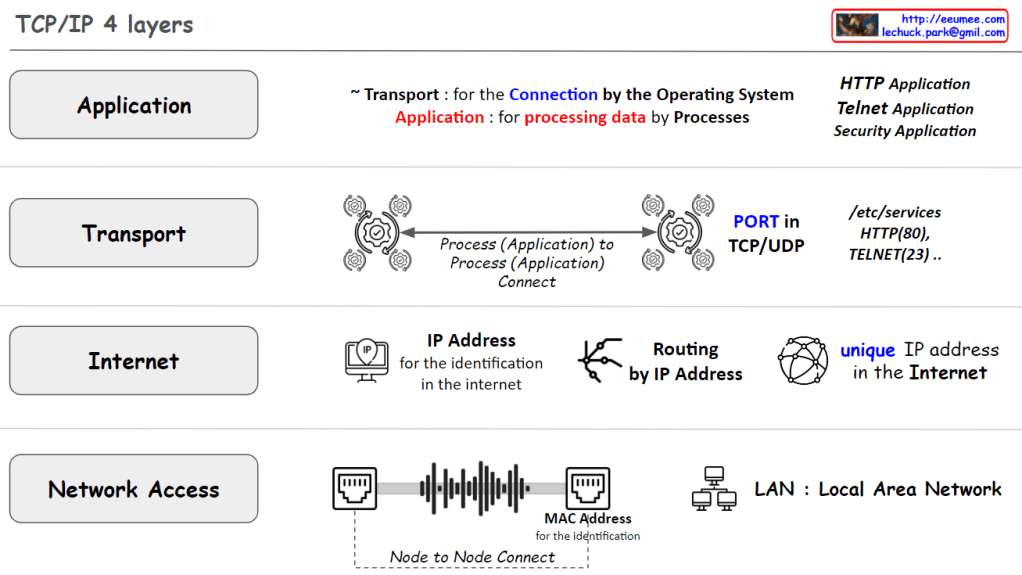
- Left Section – Network Stack:
- Application layer
- TCP/UDP layer
- IP layer
- Ethernet layer
- Middle Section – MPLS Label Structure:
- Label (20 bits): Used for routing
- Experimental (3 bits): For QoS (Quality of Service) priority
- Bottom of Stack (1 bit): Indicates if it’s the last label (Not Bottom: 0)
- TTL (8 bits): Time to Live, prevents looping
- Right Section – MPLS Network Operation:
- Label Edge Router (LER): Adds/removes labels at network boundaries
- Label Switching Router (LSR): Performs label-based switching
- Packets expire when TTL reaches 0
- Routing based on priority using Experimental (QoS) bits
Operational Flow:
- Add Label Header: When packets enter MPLS network
- Routing by Label: Packet forwarding based on labels with Priority by Exp(QoS)
- Remove Label Header: When packets exit MPLS network
Key Benefits of MPLS:
- Fast packet forwarding (label-based switching)
- QoS support
- Efficient traffic engineering
- Support for multiple network protocols
The diagram shows how MPLS creates a more efficient and manageable network by using label-based forwarding instead of traditional IP routing. Labels can be stacked (Label Stack-able) for more complex routing scenarios, and the TTL field helps prevent infinite routing loops.