Real-time Linux

with a claude’s help
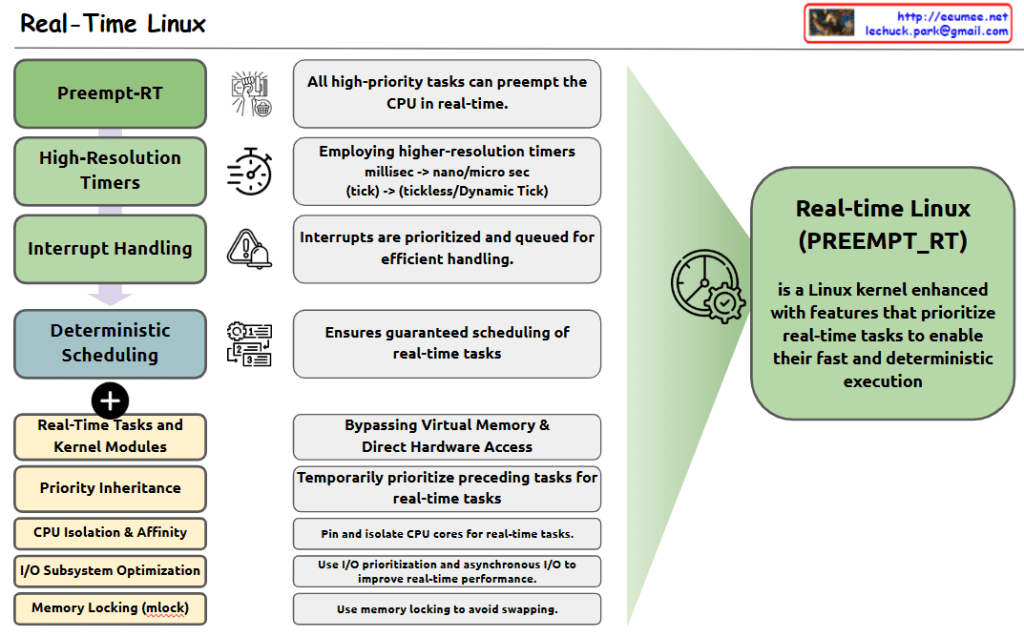
The image shows the key components and features of Real-Time Linux, which is defined as a Linux kernel enhanced with features that prioritize real-time tasks for fast and deterministic execution.

Four Main Components:

  1. Preempt-RT: All high-priority tasks can preempt the CPU in real-time.
  2. High-Resolution Timers: Employs higher-resolution timers, shifting from millisec to nano/micro sec (tick -> tickless/Dynamic Tick).
  3. Interrupt Handling: Interrupts are prioritized and queued for efficient handling.
  4. Deterministic Scheduling: Ensures guaranteed scheduling of real-time tasks.

Additional Features:

  • Real-Time Tasks and Kernel Modules
  • Priority Inheritance
  • CPU Isolation & Affinity
  • I/O Subsystem Optimization
  • Memory Locking (mlock)

Key Functionalities:

  • Bypassing Virtual Memory & Direct Hardware Access
  • Temporarily prioritize preceding tasks for real-time tasks
  • Pin and isolate CPU cores for real-time tasks
  • Use I/O prioritization and asynchronous I/O to improve real-time performance
  • Use memory locking to avoid swapping

The right side of the diagram shows the overall purpose: Real-Time Linux (PREEMPT_RT) is a Linux kernel enhanced with features that prioritize real-time tasks to enable their fast and deterministic execution.

This system is designed to provide predictable and consistent performance for time-critical applications, making it suitable for real-time computing environments where timing precision is crucial.

Memoy Leak

From Claude with some prompting
This image illustrates the process of “Memory Leak Checking”. The main components and steps are as follows:

  1. Process Is Started:
    • When a process starts, it connects through an API to a “Like Virtual Machine” environment.
    • In this environment, “Hooking” techniques are employed.
  2. Process Is Running:
    • The running process generates a “Software Interrupt” through the API.
    • There’s “Tracking syscall with Ptrace()” occurring at this stage.
  3. Memory :
    • Functions related to memory allocation, modification, and deallocation (such as malloc(), calloc(), free()) are called.
  4. Memory Leakage Management:
    • This component tracks memory Changes and Status.
  5. OS kernel:
    • OS kernel parameters about memory are involved in the process.

The diagram shows the overall process of detecting and managing memory leaks. It demonstrates how memory leaks are systematically monitored and managed from the start of a process, through its execution, memory management, and interaction with the operating system.
This diagram effectively visualizes the complex process of memory leak checking, showing how different components interact to monitor and manage memory usage in a running process.

Kernel Samepage Merging

From Claude with some prompting
This image illustrates Kernel Samepage Merging (KSM), a memory management technique used to optimize memory usage in computing systems.

Key components of the image:

  1. Top left: Icons representing disk/file systems (“almost”) and a memory grid.
  2. Memory grid: Shows memory pages filled with various letters (A-Z). Note the repeated occurrences of ‘A’ pages.
  3. Bottom: Multiple processes (Process1, Process2, Process3, Process4) sharing this memory.
  4. Right side: Explains how KSM works in four stages:
    • Searching: Locating pages with identical content.
    • Merging: Combining identical pages into one.
    • Counting: Tallying references to the merged page.
    • Updating: Refreshing page references.

KSM works by identifying and merging memory pages with identical content, thus reducing memory usage. This is particularly useful in virtualized environments where multiple virtual machines might be running similar operating systems.

The image effectively demonstrates how KSM can identify duplicate ‘A’ pages across different memory locations and processes, merging them to save memory space while maintaining proper references for each process.

Getting server data

From Claude with some prompting
This image illustrates the structure of an IPMI (Intelligent Platform Management Interface) system using BMC (Baseboard Management Controller). The main components and functions are as follows:

  1. Server: Represents the managed server.
  2. Motherboard: Depicts the server’s mainboard, where the BMC chip is located.
  3. BMC (Baseboard Management Controller): The core component for monitoring and managing server hardware.
  4. Baseboard Management Controller: Performs the main functions of the BMC, with a “Start Service” function indicated.
  5. Diff Power: Represents the server’s power management functions, including On/Off and Reset capabilities.
  6. Remote management computer: Used to remotely monitor and manage the server status.
  7. Get Server Status Remotely: Server status information that can be checked remotely, including temperature, voltage, fan speed, power consumption, system status, and hardware information.
  8. Communication process: The interaction between the remote computer and BMC is shown to involve 1) INIT (initialization) and 2) REQ/RES (request/response) stages, described as functioning similar to SNMP.

This system allows administrators to remotely monitor and control the physical state of the server.

RDMA : Remote Direct Memory Access

From Claude with some prompting
This image explains RDMA (Remote Direct Memory Access). Here’s an interpretation in English:

  1. The top of the image shows that RDMA allows one system to access the memory of another system without overheads.
  2. The bottom left box lists the main advantages of RDMA:
    • CPU Load down
    • High Bandwidth
    • Low Latency
    • Scale-out
  3. The central box describes key features of RDMA:
    • Zero-Copy
    • Direct Memory Access
    • Memory-Mapped I/O
    • Scatter-Gather I/O
  4. The bottom right box lists RDMA-related components:
    • RDMA Device
    • RDMA Protocol
    • RDMA Memory Window (defined as “a memory region accessible via RDMA”)

The image provides a concise overview of RDMA technology, highlighting its main features and benefits. It illustrates how RDMA enables efficient, direct memory access between systems, reducing CPU load and improving performance in terms of bandwidth and latency.

UNIX 1969

From Claude with some prompting
The image comprehensively illustrates the structure and major developments of the UNIX operating system, first developed in 1969. The key components and features are as follows:

  • Hardware: The foundation of the system
  • Kernel: The core of the operating system, including process management functions
  • Shell: The interface for users to manage the system
  • Utilities: Tools such as compilers included
  • Daemon: Processes that run in the background
  • C Language and Assembly: Introduced in 1972, the C language was used for system development
  • POSIX (1988): An interface for standardizing UNIX systems, including pipes and filters
  • Multitasking and Time-sharing: Key features of UNIX
  • “All is File” Philosophy: A core design principle of UNIX
  • Networking Advancements:
    • UUCP (1978): An early communication protocol between UNIX systems
    • TCP/IP with Socket API (1983): The foundation of modern networking

This diagram shows the evolution of UNIX from its basic structure to significant technological advancements over time, providing a comprehensive overview of UNIX’s core concepts and features. It displays the historical development of UNIX by combining early design elements with later added functionalities, allowing for a clear understanding of UNIX’s progression.

Kernel Transport Layer Security

From Claude with some prompting
This image illustrates the concept and structure of KTLS (Kernel Transport Layer Security). KTLS implements the TLS protocol within the Linux kernel to improve performance and security.

  1. The core functionalities of TLS (encryption, authentication, integrity, anti-replay attack, and forward secrecy) are handled within the kernel.
  2. Applications for internet services (web browsing, email, messenger, etc.) run in user space and utilize the TLS functionality through the TLS library, while still using the same socket API.
  3. Data copying (Zero-Copy) between user space and kernel space is minimized, enhancing performance.
  4. With the TLS Record Layer operating inside the kernel, context switching to user space is reduced, improving security.
  5. Cryptographic acceleration features of CPUs, such as AES-NI and other encryption instruction extensions, are utilized to boost encryption operation performance.

In summary, by moving TLS processing to the kernel level, KTLS significantly improves both performance and security simultaneously.