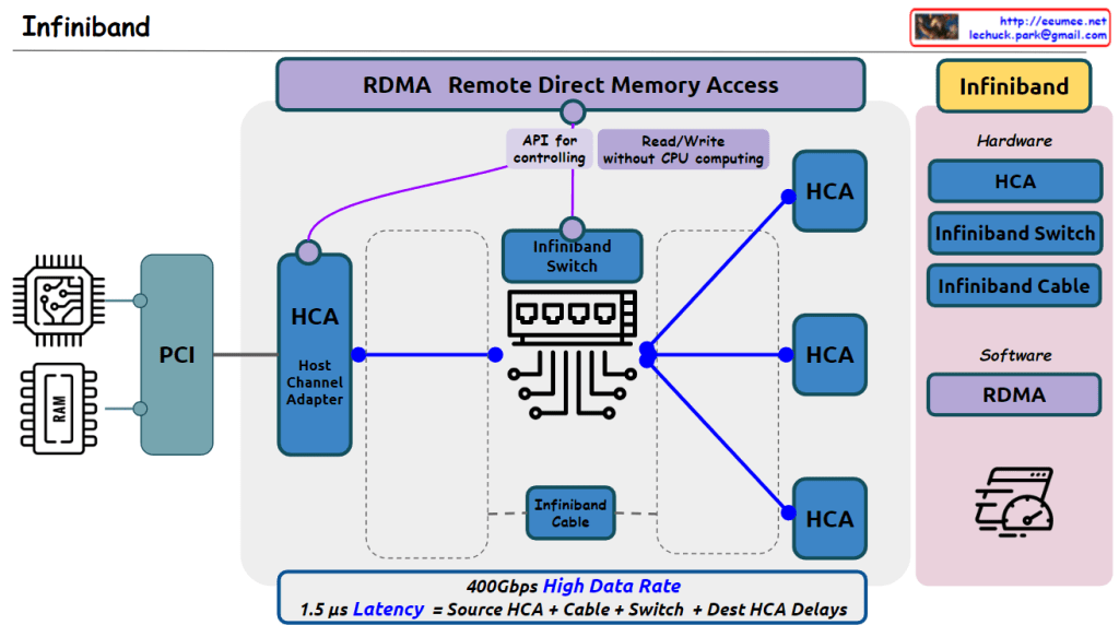
From claude with some prompting The image correctly depicts the essential hardware elements of an InfiniBand network, including the PCI interface, Host Channel Adapters (HCAs), InfiniBand Switch, and InfiniBand cables connecting the HCAs to the switch.
It highlights RDMA (Remote Direct Memory Access) as a key technology that enables read/write operations without CPU involvement, facilitated by APIs for controlling the HCAs.
The hardware components listed (HCA, InfiniBand Switch, InfiniBand Cable) are accurate.
However, there is one potential inaccuracy in the details provided. The stated latency of 1.5μs seems quite low for an end-to-end InfiniBand communication. Typical InfiniBand latencies are in the range of a few microseconds, depending on the specific InfiniBand generation and configuration.
Additionally, while the image mentions a “400Gbps High Data Rate,” it’s important to note that this is an aggregate bandwidth across multiple links or ports, not necessarily the speed of a single link.
Overall, the image effectively conveys the main concepts and components of InfiniBand technology, with just a minor potential discrepancy in the stated latency value.
From Gemini with some prompting The image illustrates how network switches differentiate packets from Layer 2 (L2) to Layer 7 (L7) based on the OSI model. The central image depicts a switch or router forwarding a specific packet, highlighting the criteria used for identification at each layer.
Layer-by-Layer Explanation:
L2 Switch:
Distinguishing criteria: MAC address
Function: Frame switching
Key feature: Uses hardware-based switching for fast performance
Limitation: Does not consider network layer information
L3 Switch:
Distinguishing criteria: IP address
Function: Packet switching, routing
Key feature: Supports inter-VLAN routing and network segmentation
Limitation: Does not utilize L4 and L7 information
L4 Switch:
Distinguishing criteria: TCP/UDP port number
Function: Packet switching, load balancing
Key feature: Facilitates application-specific traffic control and load balancing
Limitation: Disregards L7 information
L7 Switch:
Distinguishing criteria: HTTP URL, payload
Function: Application gateway, content filtering
Key feature: Offers granular control over application-level traffic and security
Complexity: Requires more complex configuration and management
From ChatGPT with some prompting The image appears to be an educational diagram explaining the basic functions and differences between three types of network devices: hubs, switches, and routers. Here’s what the image indicates about each device:
Hub: A hub is a simple networking device that broadcasts all incoming data packets to every connected device, regardless of the destination MAC address. It’s depicted as sending the same data to devices A, B, C, and D.
Switch: Unlike a hub, a switch is intelligent enough to filter and forward data packets based on their destination MAC addresses. This means it only sends the data to the specific device it is intended for, improving network efficiency and reducing collisions.
Router: A router operates at a higher level than switches and hubs. It routes data packets not just based on MAC addresses but also using IP addresses. It can connect multiple networks and manage the data traffic between them using protocols like BGP (Border Gateway Protocol).
The note at the bottom of the image states that the functions of these devices are not completely separated, and higher-level equipment includes the functions of the lower-level equipment. This means routers can perform the functions of switches, which in turn can perform the functions of hubs.
From Gemini with some prompting The image is a diagram of a network consisting of hubs, switches, and routers. The functions of each device are as follows:
Hub: A hub is a central device that connects network devices. All devices connected to a hub can communicate with each other. When a hub receives a data frame, it transmits it to all ports.
Switch: A switch is similar to a hub, but it only transmits data to the device connected to each port. A switch uses MAC addresses to determine which port to transmit a data frame to.
Router: A router is a device that connects two or more networks. A router uses IP addresses to determine which network to transmit a data packet to.
In the image, each device is connected as follows:
Computers A, B, C, D: Each computer is connected to a hub or switch.
Hub: The hub is connected to a switch.
Switch: The switch is connected to a router.
The image also includes a description of the type of data that each device handles:
Hub: The hub transmits all data frames to all ports.
Switch: The switch uses MAC addresses to determine which port to transmit a data frame to.
Router: The router uses IP addresses to determine which network to transmit a data packet to.