RPKI : Resource Public Key Infrastructure

From Claude with some prompting
RPKI (Resource Public Key Infrastructure) Overview

  1. Background of RPKI Need

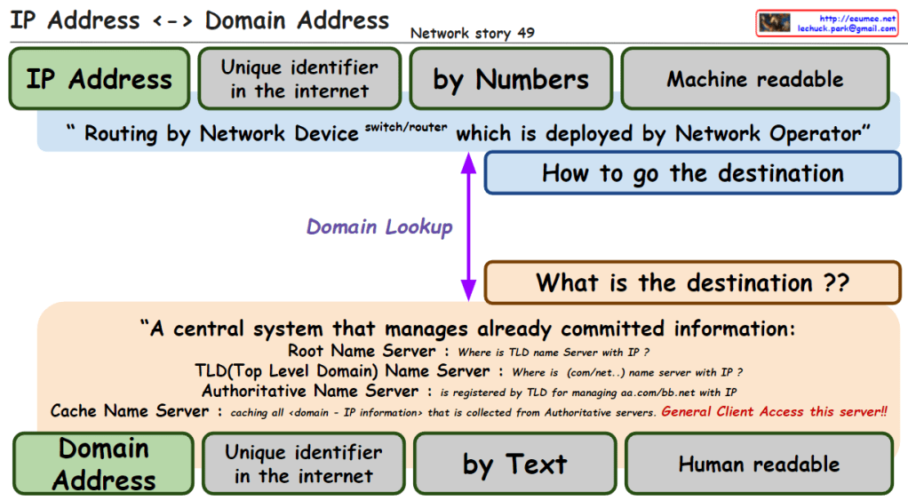
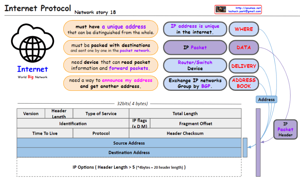
1.1. Internet requires reliable IP management

1.2. Traditional IP address and routing system vulnerabilities

1.3. Need for secure and verifiable routing infrastructure

  1. Core Components of RPKI Structure

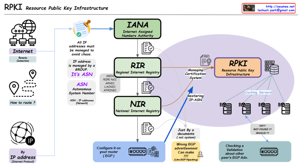
2.1. IANA (Internet Assigned Numbers Authority)

  • Top-level authority for IP resource management
  • Oversees global IP address allocation
  • Delegates authority to regional registries

2.2. RIR (Regional Internet Registry)

  • Manages continental-level resources
  • Key organizations: ARIN, RIPE NCC, APNIC, LACNIC, AFRINIC
  • Handles certification management

2.3. NIR (National Internet Registry)

  • National-level IP resource management
  • Works under RIR guidance
  • Manages local resource allocation
  1. RPKI Operational Process

3.1. Resource Management

  • IP addresses grouped by ASN (Autonomous System Number)
  • Systematic management to prevent chaos
  • Certificate-based validation system

3.2. Technical Implementation

  • Caching servers for RPKI data
  • Router configuration using BGP
  • Real-time validation of routing information
  1. Security Features

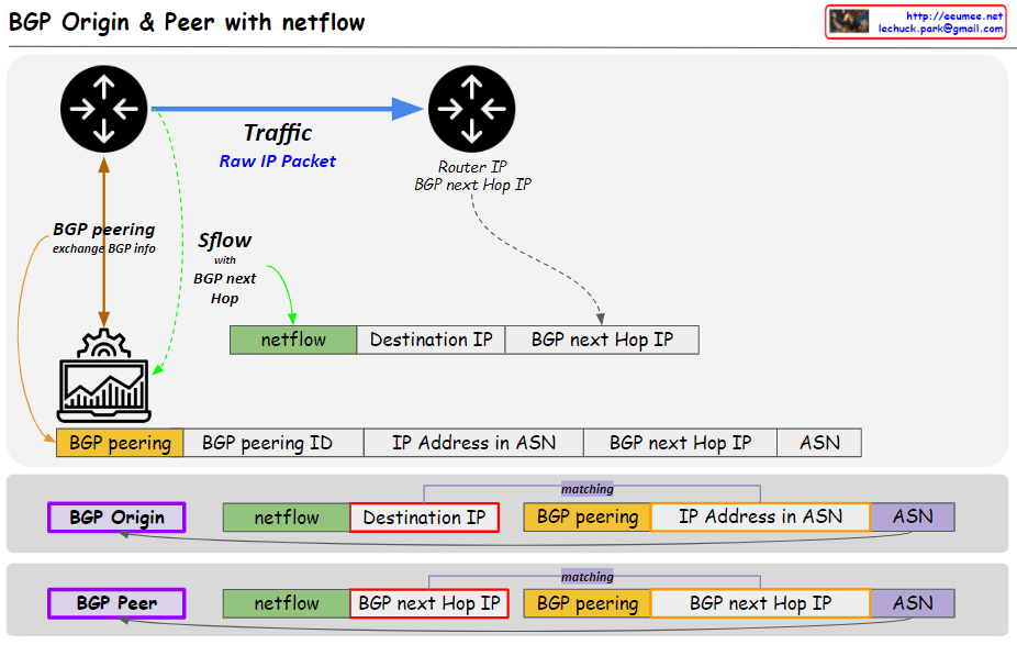
4.1. BGP Route Protection

  • Prevents BGP hijacking attempts
  • Validates peer BGP advertisements
  • Ensures routing path integrity

4.2. Validation States

  • OK: Valid route
  • NOT FOUND: No RPKI record
  • INVALID: Failed validation
  1. Benefits of RPKI

5.1. Enhanced routing security

5.2. Prevents unauthorized IP address use

5.3. Provides verifiable trust chain

5.4. Maintains internet routing stability

Summary

This RPKI-centric structure transforms traditional IP management into a robust, secure, and verifiable system for global internet routing infrastructure.

The system essentially creates a chain of trust from IANA through RIRs and NIRs down to individual network operators, ensuring the legitimacy of IP address usage and routing announcements.

Casting packet

from Claude with some prompting
This image illustrates the different types of network communication methods: Unicast, Multicast, Broadcast, and Anycast. Each method is represented by a visual diagram showing how data is transmitted from a source to specific targets or groups of targets within a network.

Unicast targets a specific IP address, sending data to a single destination. Multicast targets a specific IP group within one network, allowing data to be sent to multiple recipients simultaneously. Broadcast targets all IP addresses within a specific network, essentially sending data to every device on that network.

Anycast is slightly different, targeting a specific address but sending the data to the closest/nearest device with that address, as determined by the routing protocols and BGP (Border Gateway Protocol) peering.

The image provides a clear visual representation of these communication methods and their differences in terms of targeting and data distribution within networks.


IP network

From DALL-E with some prompting
The image presents an overview of IP network operation, emphasizing that there are two main methods by which data moves across the network. The focus is on the second method, where:

  • IP Address: Acts as the unique identifier within the internet, similar to a physical address in the real world.
  • Transmission Devices: These are network devices like switches and routers that facilitate the movement of data packets through the network.
  • Packets and Physical Connections: Data packets are routed based on their IP addresses through physical connections established within the network infrastructure.

The core message is that in an IP network, data doesn’t move on its own; it is routed based on IP addresses through devices that make the transport decisions, highlighting the importance of network infrastructure in the efficient delivery of data packets to their intended destinations.


IP & Domain address

From DALL-E with some prompting
The image explains the relationship between IP addresses and domain addresses within the context of the internet and network infrastructure. Here’s a breakdown of the components:

  1. IP Address: Identified as a unique identifier in the internet by numbers, which is machine-readable. It is used for routing by network devices like switches and routers, deployed by network operators.
  2. Domain Lookup: The process that determines how to get the destination, asking “what is the destination?”
  3. Domain Address: Also a unique identifier on the internet, represented by text, which is human-readable.
  4. Central System of Name Servers:
    • Root Name Server: Answers queries about the location of the Top-Level Domain (TLD) name server associated with an IP.
    • TLD Name Server: Provides information about the domain’s name server associated with certain domain extensions like .com or .net.
    • Authoritative Name Server: Holds the definitive records for domains within its TLD.
    • Cache Name Server: Caches all domain-to-IP information collected from authoritative servers, accessible to general clients.

The overall message emphasizes the conversion between IP addresses (numeric form) and domain addresses (text form), which is crucial for navigating the internet and finding the correct destination for data packets. It also highlights the significance of the Domain Name System (DNS) in translating between human-readable domain names and machine-readable IP addresses.