How to share access to files

From Claude with some prompting
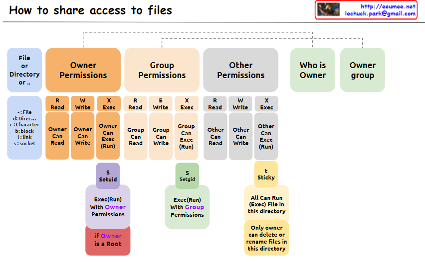
The image explains “How to share access to files” in Unix/Linux systems, illustrating the structure of file permissions. The diagram breaks down permissions into owner, group, and other categories, along with special permissions and metadata.

  1. File Permissions Structure: The image depicts how access rights to files or directories are shared in Unix/Linux systems. Permissions are divided into owner, group, and other users.
  2. Owner Permissions:
    • Read (R): Owner can read the file.
    • Write (W): Owner can modify the file.
    • Execute (X): Owner can execute the file.
  3. Group Permissions:
    • Read (R): Group members can read the file.
    • Write (W): Group members can modify the file.
    • Execute (X): Group members can execute the file.
  4. Other Permissions:
    • Read (R): Other users can read the file.
    • Write (W): Other users can modify the file.
    • Execute (X): Other users can execute the file.
  5. Metadata:
    • Who is Owner: Indicates who owns the file or directory.
    • Owner group: Shows which group the file or directory belongs to.
  6. Special Permissions: a. SetUID (S):
    • Executes with the file owner’s permissions.
    • Useful when a regular user runs the passwd command owned by root.
    b. SetGID (S):
    • Executes with the file group’s permissions.
    • Beneficial for group collaboration; new files can inherit the parent directory’s group.
    c. Sticky (T) – Corrected Part:
    • “Only owner can delete or rename files in this directory”
    • When set on a directory, files within it can only be deleted or renamed by the file’s owner, directory owner, or root.
    • Commonly used in shared directories like /tmp to prevent users from unauthorized deletion or renaming of each other’s files.
  7. Additional Information:
    • “if Owner is a Root”: When the owner is the root user, special privileges are granted. Root has all permissions on every file and directory, enabling any system administration task.

This image provides a clear and visual explanation of the file permission system in Unix/Linux. Notably, the description of the Sticky bit has been corrected to accurately reflect its function: “Only owner can delete or rename files in this directory”. This correction properly conveys that while execution and modification of files in a Sticky directory are governed by individual file permissions, the ability to delete or rename files is restricted to the file owner, directory owner, or root.

This permission system effectively manages security and accessibility in multi-user environments. It allows fine-grained control over who can read, write, or execute files, and in the case of the Sticky bit, who can delete or rename files in shared spaces. Such granular control is crucial for maintaining data integrity, privacy, and orderly collaboration among users on a Unix/Linux system.

CPU & GPU Works

From Claude with some prompting
This image explains the working principles of CPU (Central Processing Unit) and GPU (Graphics Processing Unit) in a visual manner.

  1. Data Types:
    • Scalar: A single value
    • Vector: One-dimensional array
    • Matrix: Two-dimensional array
    • Tensor: Multi-dimensional array
  2. CPU Work Method:
    • Sequential processing, denoted by ’01’
    • Tasks are processed in order, as shown by 1, 2, 3, 4, 5
    • Primarily handles scalar data, processing complex tasks sequentially
  3. GPU Work Method:
    • Parallel processing, represented by a matrix
    • Icons show multiple tasks being processed simultaneously
    • Mainly deals with multi-dimensional data like matrices or tensors, processing many tasks in parallel

The image demonstrates that while CPUs process tasks sequentially, GPUs can handle many tasks simultaneously in parallel. This helps explain which processing unit is more efficient based on the complexity and volume of data. Complex and large-scale data (matrices, tensors) are better suited for GPUs, while simple, sequential tasks are more appropriate for CPUs.

Virtual Machine & Container

From Claude with some prompting
is image compares virtual machines and containers in terms of their architecture and resource utilization. Virtual machines run a full guest operating system on virtual hardware, providing a complete system environment for applications. In contrast, containers share the host operating system kernel and use resource isolation features to run applications with their own environment configurations and software packages, resulting in a more lightweight and efficient approach.

The image shows three main sections representing virtual machines, containers, and physical machines. Each virtual machine has its own operating system and environment configurations layered on top of virtualized CPU resources. Containers, on the other hand, share the host operating system but have separate environment configurations and software packages for running applications. Physical machines form the base with their CPUs.

The key distinction is that virtual machines provide complete system isolation but have higher overhead, while containers offer application-level isolation with better resource utilization by sharing the host operating system. The choice depends on requirements for isolation, resource efficiency, and compatibility.

Register in a CPU

From Claude with some prompting
This image explains the registers within the CPU and their purposes. Registers are small, high-speed memory locations inside the CPU that serve various roles.

GPR (General Purpose Registers) are used for calculations, logical operations, etc. (like variables). SP (Stack Pointer Register) remembers the memory location of the stack for calling functions, passing parameters, and managing local variables. BP (Base Pointer Register) refers to the current/next data location within a data structure. PC (Program Counter Register) is the command currently executing, used by the CPU to decide which instruction to execute next. Status Register detects abnormalities resulting from operation performance and handles them.

It also mentions that there are more registers such as indexes, counters, timers, flags, and more.

Interrupt

From Claude with some prompting
The image illustrates the process of handling interrupts in a computer system. When an urgent job (Urgent Job Occurred) arises while another job (One Job is Working) is executing, an interrupt (Job Switching = Interrupt) occurs. This triggers the Interrupt Service Routine (ISR) to handle the interrupt.
The interrupt handling process is divided into two halves: the Top Half and the Bottom Half. The Top Half performs a “Very Short Work to avoid another job delay” and notifies the system of the interrupt occurrence. The Bottom Half handles the remaining work, also performing “Short Work to avoid another job delay.”

Memory Control Unit

From Claude with some prompting
The image explains the memory management and access approaches in computing systems. Fundamentally, for any memory management approach, whether hardware or software, there needs to be a defined unit of operation.

At the hardware level, the physical Memory Access Unit is determined by the CPU’s bit width (32-bit or 64-bit).

At the software/operating system level, the Paging Unit, typically 4KB, is used for virtual memory management through the paging mechanism.

Building upon these foundational units, additional memory management techniques are employed to handle memory regions of varying sizes:

  • Smaller units: Byte-addressable memory, bit operations, etc.
  • Larger units: SLAB allocation, Buddy System, etc.

Essentially, the existence of well-defined units at the hardware and logical/software layers is a prerequisite that enables comprehensive and scalable memory management. These units serve as the basis for memory control mechanisms across different levels of abstraction and size requirements in computing systems.

Scheduling

From Claude with some prompting
The image depicts a scheduler system that manages the allocation of computing resources, addressing the key question “Who uses computing resources?”. The main components shown are:

  1. Multiple processes or tasks are represented by circular icons, indicating entities requesting computing resources.
  2. A “Who First?? (priority)” block that determines the order or priority in which tasks will be serviced.
  3. A “Cut in Line (Interrupt)” block, suggests that certain tasks may be able to interrupt or take precedence over others.
  4. A CPU block represents the computing resources being scheduled.
  5. A “How long??” block, likely referring to the scheduling algorithm determining how long each task will be allocated CPU time.
  6. A “Slicing (Job Qsec)” block, which could be related to time slicing or dividing CPU time among tasks.
  7. Process switching and task switching blocks indicate the ability to switch between processes or tasks when scheduling CPU time.
  8. An “Algorithm & Policy” block, representing the scheduling algorithms and policies used by the scheduler.
  9. A “Multi-Core/CPU” block, explicitly showing support for multi-core or multi-CPU systems.

The image effectively covers the key concepts and components involved in scheduling computing resources, including task prioritization, interrupts, CPU time allocation, time slicing, process/task switching, scheduling algorithms and policies, and support for multi-core/multi-CPU systems. Memory management is assumed to be part of the task-switching process and is not explicitly depicted.