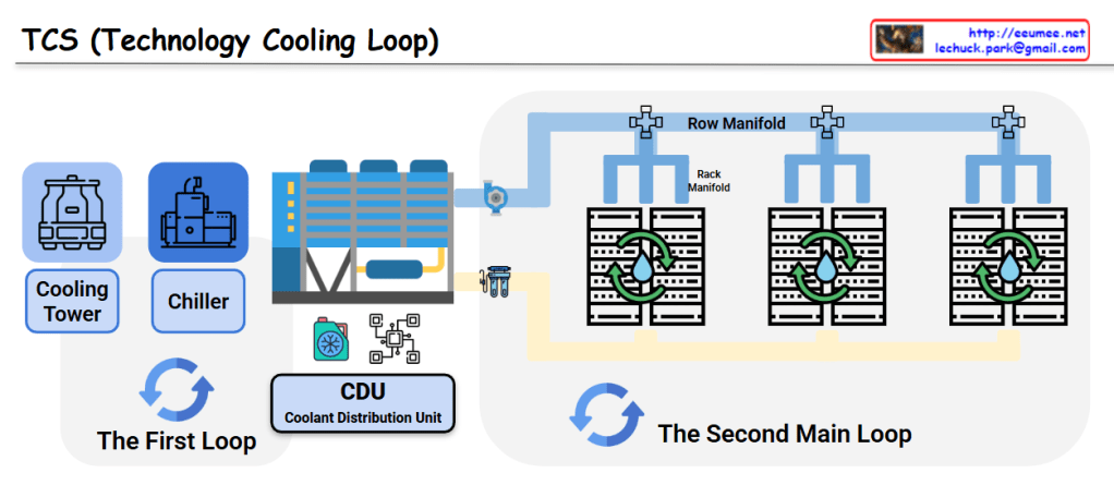
This image shows a diagram of the TCS (Technology Cooling Loop) system structure.
System Components
The First Loop:
- Cooling Tower: Dissipates heat to the atmosphere
- Chiller: Generates chilled water
- CDU (Coolant Distribution Unit): Distributes coolant throughout the system
The Second Main Loop:
- Row Manifold: Distributes cooling water to each server rack row
- Rack Manifold: Individual rack-level cooling water distribution system
- Server Racks: IT equipment racks that require cooling
System Operation
- Primary Loop: The cooling tower releases heat to the outside air, while the chiller produces chilled water that is supplied to the CDU
- Secondary Loop: Coolant distributed from the CDU flows through the Row Manifold to each server rack’s Rack Manifold, cooling the servers
- Circulation System: The heated coolant returns to the CDU where it is re-cooled through the primary loop
This is an efficient cooling system used in data centers and large-scale IT facilities. It systematically removes heat generated by server equipment to ensure stable operations through a two-loop architecture that separates the heat rejection process from the precision cooling delivery to IT equipment.
With Claude
