PING with “Don’t Fragment”

From DALL-E with some prompting
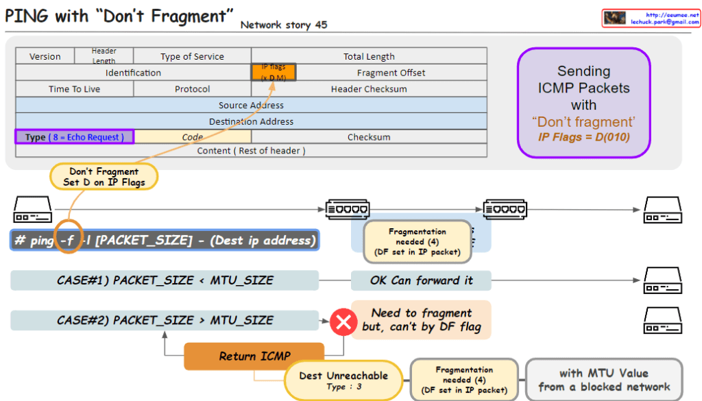
The image outlines a networking concept involving the transmission of ICMP (Internet Control Message Protocol) packets with the “Don’t Fragment” flag set, which is part of the IP (Internet Protocol) flags. Here’s a breakdown of the key elements in the image:

  1. Header Section:
    • Type of Service: Indicates the quality of service for the packet.
    • IP Flags: Contains the “Don’t Fragment” (DF) flag, indicated by setting the D bit to 0. The “MF” bit represents whether the packet is the last fragment.
    • Type: For an ICMP Echo Request, this value is set to 8.
    • Code: Used to further specify the message.
  2. Packet Transmission:
    • The command ping -f is used to send a ping with the DF flag set, which means the packets should not be fragmented, even if their size exceeds the MTU (Maximum Transmission Unit) of the network path.
    • Case #1: If the packet size is less than the MTU, the packet is forwarded without issue.
    • Case #2: If the packet size is greater than the MTU, it needs to be fragmented. However, because the DF flag is set, it can’t be fragmented, resulting in a “Destination Unreachable” message with code 3 (Fragmentation needed and DF set).
  3. Error Handling:
    • The ICMP error message “Destination Unreachable” with a code of “3” is returned if a packet with the DF flag set needs to be fragmented to continue along the network path but cannot be due to the flag.

This image is a guide to understanding how the “Don’t Fragment” flag in IP packets affects their transmission over networks and how ICMP is used for error reporting when the flag is set.

TTL(time to live) in ip packets

From DALL-E with some prompting
The image provides an educational visualization of how the “Time to Live” (TTL) value in the Internet Protocol (IP) is used to manage the life span of data packets during transmission. TTL is a crucial part of the IP header, which is decremented by each router the packet passes through. When the TTL value reaches zero, the packet is discarded, preventing it from circulating indefinitely.

The diagram outlines the following key points:

  1. ICMP Packets: It shows the process of sending ICMP (Internet Control Message Protocol) packets, specifically an Echo Request, which is a common method for pinging a destination IP address to test connectivity.
  2. TTL Decrement: Each hop in the network decreases the TTL value of the packet by one. This decrement process helps determine how many network hops the packet has passed through to reach its destination.
  3. TTL in Action: The sequence of routers illustrates the TTL value decreasing from 64 down to 57 as the packet travels across seven network hops.
  4. Command Usage: It includes a command line example # ping -t [ttl] (Dest ip address) that specifies how to ping with a defined TTL value.
  5. TTL Analysis: It suggests that analyzing TTL values can help detect anomalies in packets, changes of routes from the same peer IP address, among other uses. For example, receiving a packet with an unusually high TTL value like 500 could indicate an abnormality.
  6. Receiving and Responding: The final part of the image shows a receiving computer that gets the ICMP packet with a TTL of 57 and replies with an Echo Response.

This visual aid is likely used for educational purposes to teach about network packet management, routing, and network troubleshooting techniques.

ICMP2

From DALL-E with some prompting
The image introduces the overarching functionality of the Internet Control Message Protocol (ICMP). ICMP serves to provide feedback when network equipment cannot further forward packets, explaining the reasons via messages indicating destination unreachable, time exceeded, parameter problems, among others. It also includes the redirect function, suggesting better routing paths between network devices, thus enhancing the overall network efficiency. Fundamentally, ICMP operates on a request and reply structure, which is essential for checking network status and diagnosing issues.